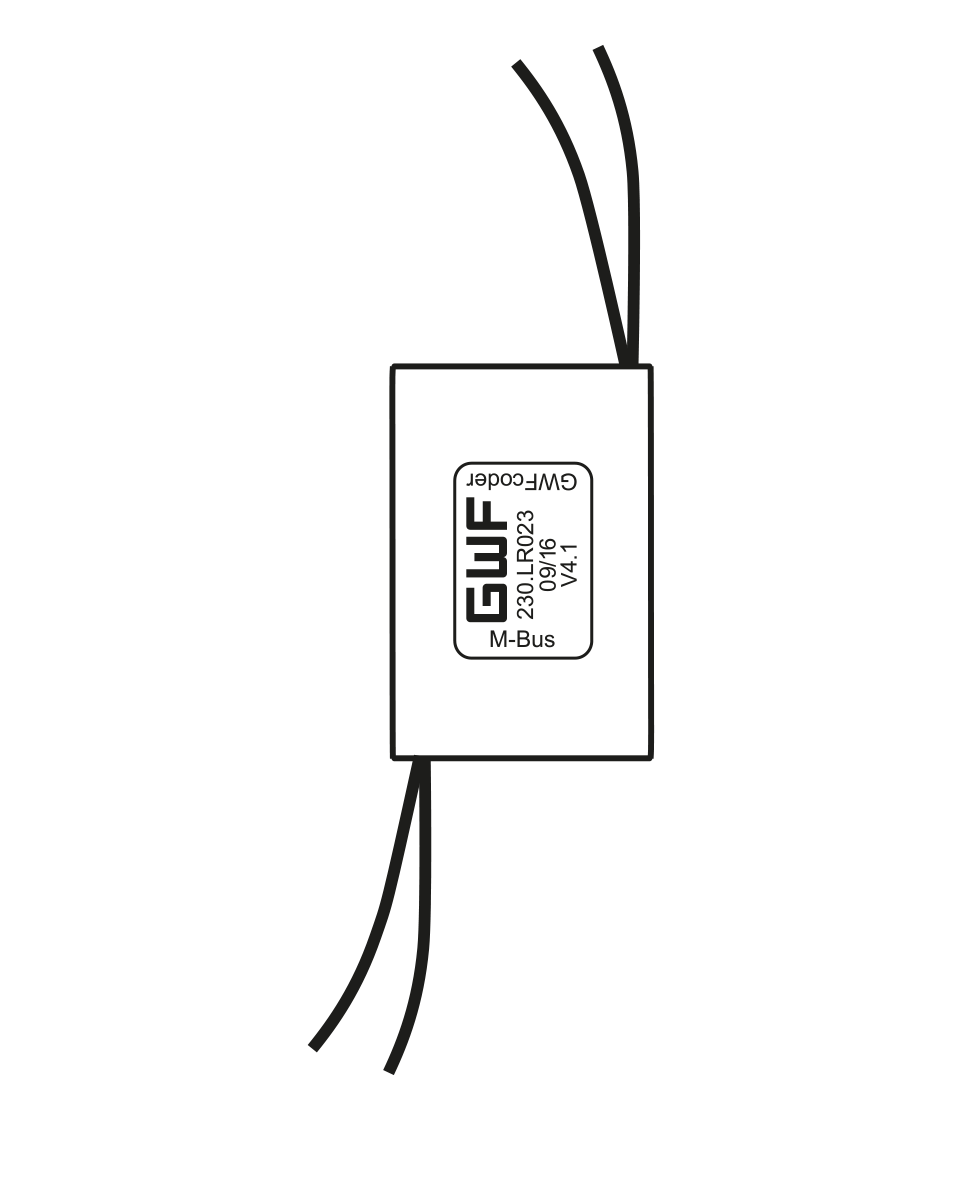
GWFcoder®-Interface
M-Bus - SCR P
Product categories
Water,
Heat / Cooling,
Gas
Remote meter reading
Water
Drinking Water
Heat / Cooling
Gas
System technology
Smart City
Your benefits
- Interface converter between SCR(IEC) and M-Bus:
Conversion without meter exchange - Automatic allocation of primary address:
Simplified start-up of electric meters with integrated M-Bus master interface (Smart Metering) - Simplifies logistics:
Only meters with SCR(IEC) must be keep on stock - Polarity independent:
Easy on-site installation
Applications
- Using the interface, installed GWFcoder® cold water meters and gas meters can be readout via an M-Bus master (except BGZcoder® MP and MTKcoder® MP)
- Several meters can be interconnected and readout via the M-Bus
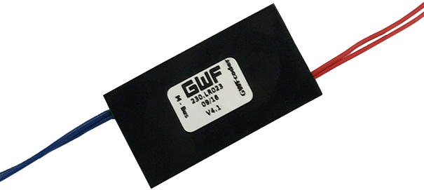
Properties
- Data compatibility – for the M-Bus master, the interface acts like a GWFcoder® meter with integrated M-Bus
- Adjustable parameters for baud rate and primary address
- Due to the connected meter, the primary address is automatically defined:
Water meter = Primary address 1
Gas meter = Primary address 2 - 4 M-Bus unit loads (6 mA) per GWFcoder® register (Version ≤3.0)
- 5 M-Bus unit loads (7,5 mA) per GWFcoder® register (Version ≥4.0)
- Polarity independent connection of GWFcoder® meter to the interface
- Using the interface, the GWFcoder® meter (cold water and gas) with SCR(IEC) interface can be integrated in a new or existing M-Bus network with other M-Bus meters. In combination with remote meter readout, it is possible to readout register readings directly from a control centre via a modem. The interface automatically reads out the GWFcoder® register at specified intervals and saves the current data set in the internal memory. If the readout occurs via the M-Bus, the data is immediately available and transferred to the control centre. The remote meter readout software must support the GWFcoder® data set.
Product information
Components

General performance
- The waiting period after Power «ON» is max. 15 s. The interface reads out data automatically from the GWFcoder® register.
- After successful reading of the GWFcoder® register, the interface can be selected and readout via the M-Bus master.
- Due to the connected meter, the primary address is automatically defined (water = 1, gas = 2). If the installer programs a different primary address the automatic allocation of primary addresses is permanently deactivated.
- The readout software must support the data interpretation of the GWFcoder® data set. The data set is compatible with the data set of GWFcoder® registers with integrated M-Bus. This data set is already supported by the majority of suppliers.
Readout interval
- The register reading is updated in the interface after each readout and every 15 min.
- If the meters in the M-Bus network are read-out in a cyclic manner, there should be a pause of at least 15 s at the end of the cycle.
- The interface readout interval should not be less than 15 s.
Commissioning
- During commissioning the parameters for the baud rate and, in case of use of the primary address, for the address must entered. The interface reads out the secondary address directly from the GWFcoder® register.
- After exchanging the meter, the M-Bus must be restarted (Power «ON/OFF») and the meter list in the readout software adjusted.
- After exchanging the interface, the parameters of the baud rate and, if necessary, the primary address must be adjusted.
Technical Data
| Data transfer | |
|---|---|
| Baud rate | 2400 baud (default) or 300 baud |
| Primary address | Water meter = 1 (automatic) Gas meter = 2 (automatic) Automatic allocation of primary address only possible for interface modules ≥V3.0 1-250 (by installer) |
| Secondary address | Meter number (eight digits) |
| M-Bus unit load | |
|---|---|
| Load | 4 M-Bus unit loads (6 mA) per GWFcoder® register SCR(IEC) (Version ≤3.0) 5 M-Bus unit loads (7,5 mA) per GWFcoder® register SCR(IEC) (Version ≥4.0) |
| Installation | |
|---|---|
| The interface can be installed at the M-Bus master or the meter. | |
| Max. cable length | |
|---|---|
| SCR connection cable | 150 m |
| M-Bus connection cable | Network-dependent |
| Dimensions and weights | |
|---|---|
| Dimensions | 50 x 26 x 11 mm (+ 2 x 85 mm cable) |
| Weight | app. 20 g |
| Application area | |
|---|---|
| Temperature | -10 to + 60 °C |
| Protection class | IP54 |
| Interfaces | |
|---|---|
| M-Bus acc. to EN 13757-2 | |
| SCR / Protocol IEC 62056-21 | |
| Supported meters | |
|---|---|
| GWFcoder® cold water and gas meters with SCR(IEC) interface (except BGZcoder® MP and MTKcoder® MP) | |
| Connection and signal transfer | |
|---|---|
| M-Bus (blue) | M-Bus master acc. to EN 13757-2 After Power «ON», the interface requires app. 15 s before it is ready for operation. |
| GWFcoder® (red) | GWFcoder® register (polarity independent) |