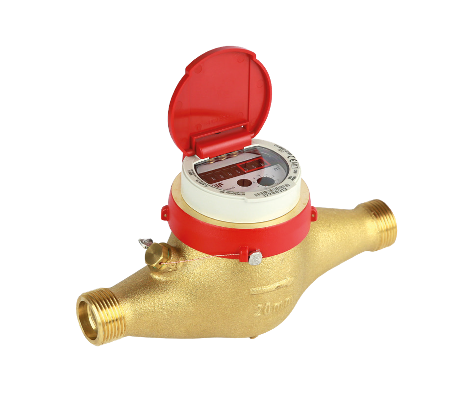
Multijet meter
MTWcoder® MP
Product categories
Multijet meter with M-Bus interface EN 13757-2 for warm water up to 90 °C
Water
Drinking Water
Mechanical
Wired
M-Bus
Wireless
wM-Bus,
LoRaWAN
Smart Building
Your benefits
- Mechanical roller register with 1-litre resolution:
Efficient consumption monitoring in energy data management - Transfer of the effective meter reading:
No data loss and guaranteed security of the billing data - Register without batteries:
No service life restriction - Robust, high grade wear resistant materials:
Excellent measuring stability and reliability - Measurement of low flow rates:
Increased cost effectiveness
Applications
- Residential consumption monitoring of water consumption within an entire building
- For nominal flow rates up to 25 m3/h
- Water meter with M-Bus data communication
Options
- NPSM threaded connection (only for horizontal housing)
Links
NSF certificateProperties
- Multijet impeller wheel, super dry-dial, magnetic coupling
- 8 dial resolution with 3 comma place
- Register can be turned for best readout position
- Maximum operation pressure PN 16 bar
- Maximum operating temperature 90 °C
- Horizontal or vertical installation (MTW-V…)
- High grade wear resistant and corrosion proof materials
- Inlet strainer
- KTW and W270 Certification
 Conformity according to European Measuring Instruments (MID)
- Serial M-Bus interface to EN 13757-2/3
- Power is provided from the M-Bus central
- Connecting cable, standard length 1,5 m
- SVGW certification
Product information
Technical Data
| Execution | MTWcoder ® MP (horizontal) | MTWcoder ® MP-VS or -VF (vertical)1) | |||||||||||
|---|---|---|---|---|---|---|---|---|---|---|---|---|---|
| Nominal diameter | DN | mm | 15 | 20 | 25 | 25 | 32 | 40 | 50 | 20 | 25 | 32 | 40 |
| Operating pressure | PN | bar | 16 | 16 | 16 | 16 | 16 | 16 | 16 | 16 | 16 | 16 | 16 |
| Connection thread on meter | G…B | Inch | ¾ | 1 | 1¼ | 1¼ | 1½ | 2 | 2⅜ | 1 | 1¼ | 1½ | 2 |
| Connection thread on coupling | R… | Inch | ½ | ¾ | 1 | 1 | 1¼ | 1½ | 2 | ¾ | 1 | 1¼ | 1½ |
| Nominal flow rate | Q3 | m3/h | 2,5 | 4 | 6,3 | 10 | 10 | 16 | 25 | 4 | 6,3 | 10 | 16 |
| Maximum flow rate | Q4 | m3/h | 3,125 | 5 | 7,875 | 12,5 | 12,5 | 20 | 31,25 | 5 | 7,875 | 12,5 | 20 |
| Transitional flow rate ± 3 % | Q2 | l/h | 40 | 80 | 126 | 200 | 200 | 320 | 500 | 80 | 126 | 200 | 320 |
| Minimum flow rate ± 5 % | Q1 | l/h | 25 | 50 | 78,75 | 125 | 125 | 200 | 312,5 | 50 | 78,75 | 125 | 200 |
| Temperature | max.°C | 90 | 90 | 90 | 90 | 90 | 90 | 90 | 90 | 90 | 90 | 90 | |
| Measuring range | R100 | R80 | R80 | R80 | R80 | R80 | R80 | R80 | R80 | R80 | R80 | ||
| Dimensions and weights | MTWcoder® MP (horizontal) | MTWcoder® MP-VS or -VF (vertical)1) | |||||||||||
|---|---|---|---|---|---|---|---|---|---|---|---|---|---|
| Length without couplings | A | mm | 165 | 2202) | 260 | 260 | 260 | 300 | 300 | 105 | 150 | 150 | 200 |
| Length with couplings | mm | 239 | 312 | 352 | 352 | 372 | 432 | 452 | 197 | 242 | 262 | 332 | |
| Meter height with lid | B | mm | 119 | 125 | 135 | 135 | 135 | 160 | 174 | - | - | - | - |
| Meter height with lid from pipe centre line | C | mm | 84 | 85 | 91 | 91 | 91 | 114 | 117 | - | - | - | - |
| Meter depth with lid | D | mm | - | - | - | - | - | - | - | 148 | 169 | 183 | 226 |
| Meter depth with lid from pipe centre line | E | mm | - | - | - | - | - | - | - | 130 | 143 | 156 | 190 |
| Installation depth with lid from pipe centre line | W | mm | 48 | 48 | 50 | 50 | 50 | 68 | 76 | 48 | 49 | 51 | 70 |
| Meter height with open lid | G | mm | 167 | 173 | 183 | 183 | 183 | 208 | 222 | - | - | - | - |
| Weight without couplings | app. kg | 1,7 | 2,1 | 2,6 | 2,6 | 2,7 | 5,4 | 6,7 | - | - | - | - | |
| Weight without couplings MTW-VS | app. kg | - | - | - | - | - | - | - | 1,9 | 3,0 | 3,0 | 6,0 | |
| Weight without couplings MTW-VF | app. kg | - | - | - | - | - | - | - | 2,0 | 3,4 | 3,7 | 7,3 | |
| Weight with couplings | app. kg | 1,9 | 2,3 | 3,0 | 3,0 | 3,3 | 6,4 | 8,7 | - | - | - | - | |
| Weight with couplings MTW-VS | app. kg | - | - | - | - | - | - | - | 2,1 | 3,4 | 3,6 | 7,0 | |
| Weight with couplings MTW-VF | app. kg | - | - | - | - | - | - | - | 2,2 | 3,8 | 4,3 | 8,3 | |
1) -VS = vertical riser / -VF = vertical down pipe 2) Also supplied in length 190 mm
Dimension Diagram

Materials
| Housing: | UBA Brass (DIN 50930-6) |
| Sealing plate: | UBA Brass (DIN 50930-6) |
| Impeller / measuring insert: | High grade synthetic materials |
| Bearings: | Hard metal, Sapphire, Chrome nickel steel |
| Seal material: | EPDM |
| Information | |
|---|---|
| EU-REACH Art. 33 / ChemV Art. 71 | Brass products contain lead > 0,1 % |
Measuring error curve

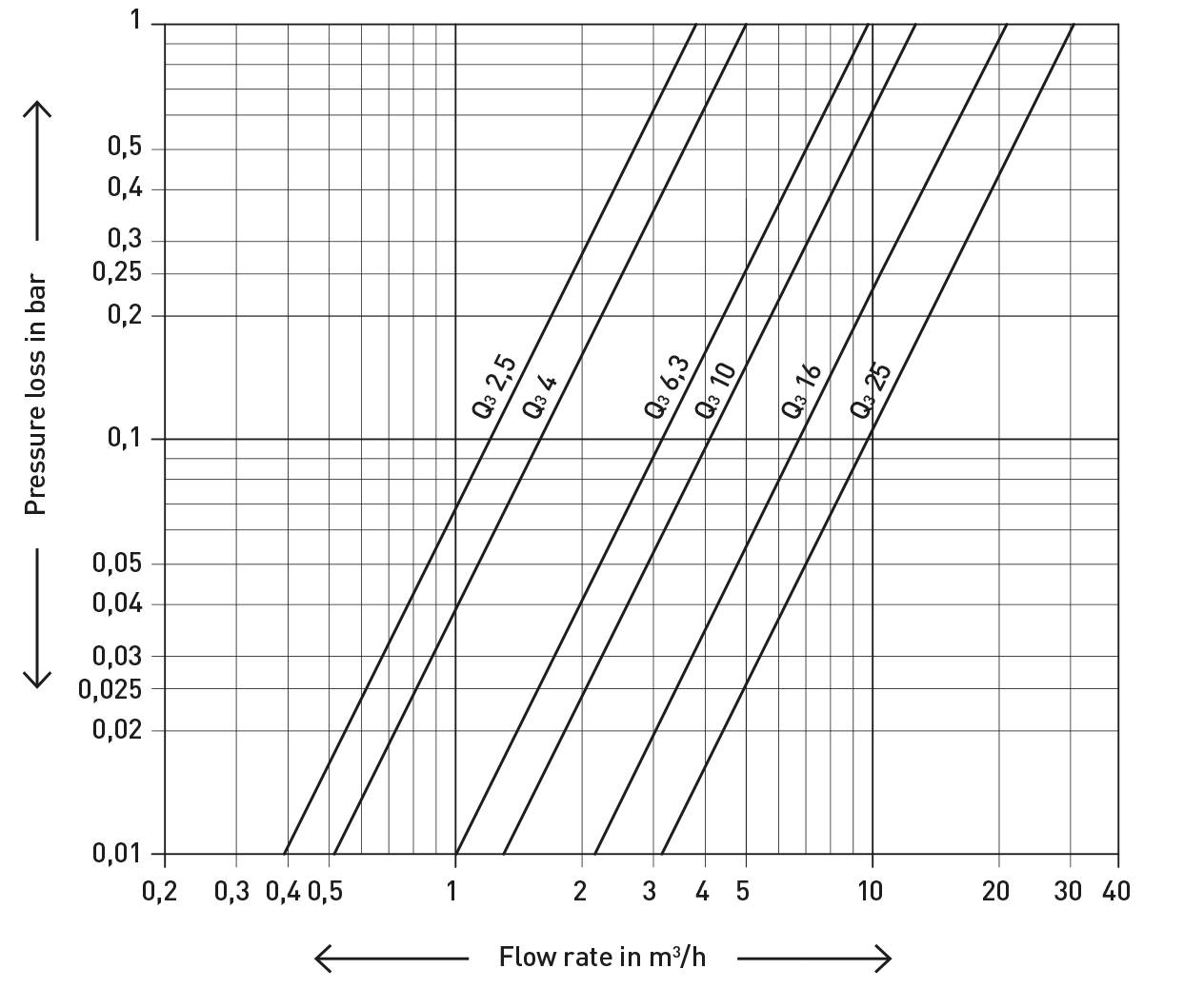
Typical Head Loss Curve
Installation
| Pipeline: | horizontal | |
| vertical | ||
| Meter head: | upwards |
Installation Requirements
The meter must be installed so that the type plate is always horizontally positioned, facing upwards (do not tilt).
![]() Documentation: GWF water meters - BAdfei10207
Documentation: GWF water meters - BAdfei10207
GWFcoder®-Technology
The 2nd generation
The well-established GWFcoder®-system reads the absolute mechanical register value precisely and reliably and provides the data through standardized interfaces. The number wheels with three various long, asymmetrically arranged slots are being scanned through light pipes which are connected to five light emitting diodes (LED). Thus, the exact position of each number wheel can be detected and the encoded absolute register read can be transmitted as part of the M-Bus protocol. This functioning principle is patented by GWF. The GWFcoder®-interface provides an incomparably higher level of information compared to meters with pulse output.
GWF enhanced the reliable technology in its 2nd generation, so that 8 instead of 5 number wheels are being scanned and therefore a resolution of 1 liter is possible.