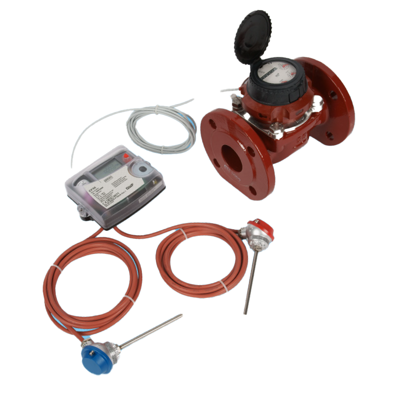
Combined heat and cooling meter for large measuring points
CF-51 and CF-55
Product categories
Heat / Cooling
Combined heat and cooling meter for large measuring points
Heat / Cooling
Mechanical
Ultrasonic
Magnetic-Inductive
Smart Building
Your benefits
- Big display:
- Easy to read - Universal applicable:
- Wall-mounted model
- Different power supply possibilities - Option cards for diverse functionalities:
- Economical base device
- Additional functionalities feasible
Applications
- Metering of heat and/or cooling consumption in building management
- Energy measurement for local or remote reading
- Application for large measuring points
Options
- Special version for combined heat/cold measurements (special programming)
- Option cards for:
- M-Bus / water meter inputs
- M-Bus / 2 pulse outputs
- Heat energy: Output Heat energy + volume
- Heat and cooling energy: Output Heat and cooling energy
- M-Bus Power / 2 water meter inputs
- Double M-Bus (only CF-55)
- LonWorks, FTT-10A / 2 water meter inputs (separate supply 24 V AC/DC necessary)
- Modbus RTU (RS485) / 2 water meters inputs (Power supply module 230 V AC necessary) - Optional external EquaScan - wireless pulse Module pMIU
 Documentation: CF-51 Calculator - EPe20526 Documentation: CF-55 Calculator - EPe20527
Downloads
Electrical scheme CF 51
Electrical scheme CF 55
Electrical scheme Axonic CF-51 (german)
Electrical scheme Axonic CF-55 (german)
Electrical scheme Optiflux CF-51 UD (german)
Electrical scheme Optiflux CF-51 BD (german)
Electrical scheme Optiflux CF-55 UD (german)
Electrical scheme Optiflux CF-55 BD (german)
CF-51/55 calculator installation und operating instructions
Option card CF-calculator (German)
Option card M-Bus Power CF-calculator (German)
Option card LONWORKS CF-calculator (German)
Properties
- Electronic calculator and LCD-resolution 7 digits
- Temperature measuring range 0 - 180 °C
- Temperature sensor Pt 100
- CF-51: 2-wires
- CF-55: 2- or 4-wires - Non-volatile memory EEPROM and 24 month register
- Supply via 12-year battery, mains or M-Bus (pay attention to versions)
- Maximum values with time stamp
- Can be combined with the following volume measuring meters:
- Mechanical impeller meters
- Ultrasonic meters with Reed-pulser
- MID - Standard EN 1434
 Conformity according European Measuring Instruments Directive (MID)
Product information
Technical Data MTW / MTW-VS / MWT-VF / MTH

Dimension Diagram CF51 / CF-55 / MTW(-V) / MTH(-V)

Technical Data WPD FS
| Series | WPD FS | ||||||||||||
|---|---|---|---|---|---|---|---|---|---|---|---|---|---|
| Nominal diameter | DN | mm | 50 | 50 | 65 | 65 | 80 | 80 | 100 | 100 | 125 | 150 | 150 |
| Operating pressure | PN | bar | - | - | - | - | - | - | - | - | - | - | - |
| Operating pressure (flanged) | PN | bar | 16 | 16 | 16 | 16 | 16 | 16 | 16 | 16 | 16 | 16 | 16 |
| Connecting thread on meter | G…B | Zoll | - | - | - | - | - | - | - | - | - | - | - |
| Connecting thread on coupling | R… | Zoll | - | - | - | - | - | - | - | - | - | - | - |
| Nominal flow rate | qp | m3/h | 15 | 15 | 25 | 25 | 40 | 40 | 60 | 60 | 100 | 150 | 150 |
| Maximum flow rate | qs | m3/h | 30 | 30 | 50 | 50 | 80 | 80 | 120 | 120 | 200 | 300 | 300 |
| Minimum flow rate ±5% | qi | m3/h | 1,5 | 1,5 | 2,5 | 2,5 | 4 | 4 | 6 | 6 | 10 | 15 | 15 |
| Pulse value of volume measuring meter | l/Imp. | 25 | 25 | 25 | 25 | 25 | 25 | 25 | 25 | 100 | 250 | 250 | |
| Kvs-value | m3/h | 110 | 110 | 110 | 110 | 340 | 340 | 380 | 380 | 520 | 810 | 810 | |
| Temperature range | °C | 10... 130 | 10... 130 | 10... 130 | 10... 130 | 10... 130 | 10... 130 | 10... 130 | 10... 130 | 10... 130 | 10... 130 | 10... 130 | |
| Installation position | ←→ ↑↓ | ←→ ↑↓ | ←→ ↑↓ | ←→ ↑↓ | ←→ ↑↓ | ←→ ↑↓ | ←→ ↑↓ | ←→ ↑↓ | ←→ ↑↓ | ←→ ↑↓ | ←→ ↑↓ | ||
| Standard measuring range | qi/qp | 1:10 | 1:10 | 1:10 | 1:10 | 1:10 | 1:10 | 1:10 | 1:10 | 1:10 | 1:10 | 1:10 | |
| Dimensions | WPD FS | ||||||||||||
|---|---|---|---|---|---|---|---|---|---|---|---|---|---|
| Length without couplings | A | mm | - | - | - | - | - | - | - | - | - | - | - |
| Length with couplings | mm | - | - | - | - | - | - | - | - | - | - | - | |
| Total height | B | mm | - | - | - | - | - | - | - | - | - | - | - |
| Meter height from pipe centre line | C | mm | 120 | 120 | 120 | 120 | 150 | 150 | 150 | 150 | 160 | 177 | 177 |
| Meter depth | D | mm | - | - | - | - | - | - | - | - | - | - | - |
| Meter depth from pipe centre line | E | mm | - | - | - | - | - | - | - | - | - | - | - |
| Meter width | F | mm | - | - | - | - | - | - | - | - | - | - | - |
| Length with flanges | A | mm | 200 | 270 | 200 | 300 | 225 | 300 | 250 | 360 | 250 | 300 | 500 |
| Height with flanges | H | mm | 193 | 193 | 205 | 205 | 245 | 245 | 255 | 255 | 278 | 312 | 312 |
| Flange external dimension 3) | D | mm | 165 | 165 | 185 | 185 | 200 | 200 | 220 | 220 | 250 | 285 | 285 |
| Hole circle diameter messer 3) | L | mm | 125 | 125 | 145 | 145 | 160 | 160 | 180 | 180 | 210 | 240 | 240 |
| Number of screws 3) | Stk. | 4 | 4 | 4 | 4 | 8 | 8 | 8 | 8 | 8 | 8 | 8 | |
3) DIN EN 1092-2
Dimension Diagram WPD FS

Technical Data AXONIC / OPTIFLUX 4300

Dimension Diagram AXONIC / OPTIFLUX 4300

Calculator executions
Wall-mounted model (split version)
CF-51
■ ... WBT Battery (12 years)
■ ... WNZ Mains supply (230 V AC)
■ ... WFS Supply via M-Bus
CF-55
■ ... WBT Battery (12 years)
■ ... WNZ Mains supply (230 V AC)
■ ... WFS Supply via M-Bus