GWFcoder®-Interface
M-Bus/SCR - SCR MP (IEC)
Product categories
Water,
Heat / Cooling,
Gas
Remote meter reading
Water
Drinking Water
Heat / Cooling
Gas
Smart City
Your benefits
- Interface multiplication:
Multiple use of meter data - Use of a GWFcoder® meter with SCR(IEC) interface in a M-Bus network:
Meter data can be made available to the end customer - Labeled connection terminals:
Easy on-site installation
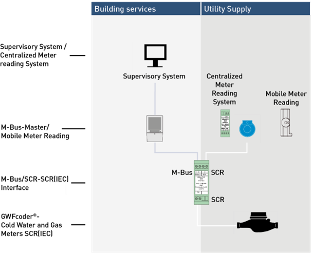
Applications
- With the interface, water and gas meters equipped with GWFcoder® registers can be read by the utility for billing purposes as well as by the building technology system for energy optimization.
Properties
- Data Compatibility – For the M-Bus master, the interface behaves like a GWFcoder® meter with integrated M-Bus.
- Polarity-independent connection of GWFcoder® meters to the interface.
- DIN rail mounting
- GWFcoder® meters with SCR(IEC) interface provide both an SCR(IEC) and a M-Bus interface simultaneously when used with the interface. The interface automatically reads the GWFcoder® register at predefined intervals and stores the current data record in its internal memory. When a readout is performed via the M-Bus or the SCR(IEC) interface, the data is immediately available and transmitted to the master.
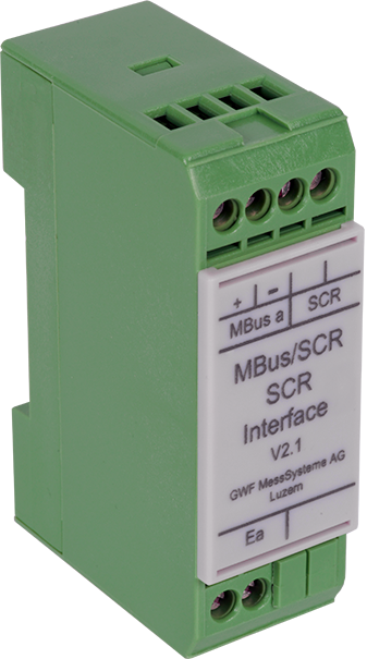
Product information
Components
General Operating Behavior
- The start-up time after power ON is max. 15 s. The interface automatically reads the data from the GWFcoder® register.
- After successful readout of the GWFcoder® register, the interface can be selected and read out by the M-Bus master.
- The readout software must support interpretation of the GWFcoder® data record. The data record is compatible with the data record of GWFcoder® meters with integrated M-Bus. This data record is already supported by most providers.
Readout Interval
- The meter reading is updated in the interface after each readout and additionally every 15 min.
- If the meters are read cyclically within the M-Bus network, a pause of at least 15 s must be observed at the end of each cycle.
- The readout interval of the interface must not be less than 15 s.
Commissioning
- During commissioning, the baud rate for «M-Bus a» and «M-Bus b» must be verified and, when using primary addressing, the address must be parameterized. The secondary address is read directly by the interface from the GWFcoder® register.
- «M-Bus a» must be connected, as the interface is powered via this connection.
- After replacing a meter, «M-Bus a» must be restarted (power ON/OFF), and the meter list of both M-Bus networks must be updated in the readout software.
- After replacing the interface, the baud rate and, if applicable, the primary address must be reconfigured.
Meter Connection Scheme
| Meter Type | Connection Wires | |
|---|---|---|
| MTKcoder® IP67 | Without approval, | white, brown |
| MTKcoder® IP68 | Without approval, | black, red (cut green wire) |
| MTKcoder® MP IP67 | white, brown | |
| MTKcoder® MP IP68 | black, red (cut green wire) | |
| WPDKcoder WSDKcoder Meitwin with GWFcoder® WPVD with GWFcoder® | Without approval | black, red (cut brown wire) |
| Meistream with GWFcoder® Meistream Plus with GWFcoder® Meitwin with GWFcoder® WPV-MS with GWFcoder® | white, brown | |
| Meistream with GWFcoder® MP Meistream Plus with GWFcoder® MP Meitwin with GWFcoder® MP WPV-MS with GWFcoder® MP | black, red (cut green wire) | |
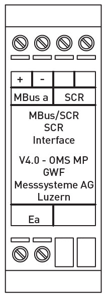
| Connection and Signal Transmission / Interface | |
|---|---|
| M-Bus a +/- | M-Bus master acc. to EN 13757-2, supervisory system. After power «ON», the interface requires 15 s to become operational. Power supply via «M-Bus a». |
| SCR | M-Bus master according to EN 13757-2, supervisory system. After power «ON», the interface requires 15 s to become operational. |
| Ea | GWFcoder® register (polarity-independent) |
Technical Data
| Data Transmission – M-Bus | |
|---|---|
| Baud rate | 2400 Baud (Standard) or 300 Baud |
| Primary address | 1–250 |
| Secondary address | GWFcoder® meter number – 8 digits, numeric |
| Data Transmission – SCR(IEC) | |
|---|---|
| Compatibility | Wall module, CL socket, radio module RCM®-PI 2, CL-SCR interface, RS232-SCR interface; from version ≥ 4.2: RCM® split, RCM®-LRW… |
| M-Bus Load | |
|---|---|
| Load | M-Bus a: 5 M-Bus unit loads (7,5 mA – supply) |
| Installation | |
|---|---|
| The interface can be installed at the M-Bus master or at the meter. | |
| Maximum Cable Length | |
|---|---|
| SCR connection cable | 150 m |
| M-Bus connection cable | Depending on network configuration |
| Dimensions and weights | |
|---|---|
| Dimensions | 25 x 78 x 47 mm |
| Weight | app. 50 g |
| Operating Conditions | |
|---|---|
| Temperature | -10 to + 60 °C |
| Protection class | IP40 |
| Interfaces | |
|---|---|
| M-Bus acc. to EN 13757 | |
| Inductive via SCR / protocol IEC 62056-21 | |
| Supported Meters | |
|---|---|
| GWFcoder® cold water and gas meters with SCR(IEC) interface | |