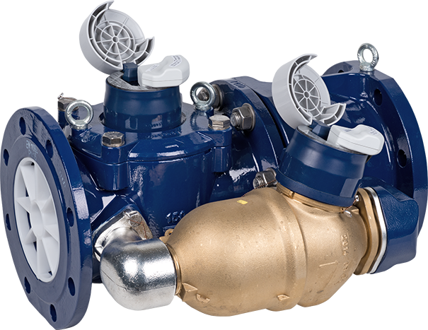
Verbundzähler
WPV-MS mit GWFcoder® MP
Product categories
Verbundzähler mit GWFcoder®-Zählwerk MP für Kaltwasser bis 50 °C
Water
Drinking Water
Mechanical
Smart City
Your benefits
- Revolutionäre Multiprotokoll-Schnittstelle (IEC und M-Bus in einem Zähler):
Investitionsschutz aufgrund der Interoperabilität des Zählers - Übertragung des effektiven Zählwerkstandes:
Kein Datenverlust und somit Sicherheit bei der Verbrauchsabrechnung - Keine Einsatzzeit beschränkende Batterie:
Wartungsfrei - Messung kleinster bis grösster Durchflüsse:
Erhöhung der Wirtschaftlichkeit
Applications
- Messung hoher, stark schwankender Durchflussmengen, z. B.:
- Gewerbe- und Industrieanlagen
- Schul- und Sportkomplexe
- Wohnblöcke
- Hotels - Vorgegebene Leitungsdimensionierung für Feuerlöschwasserbedarf
- Automatisierte mobile oder Festnetzauslesung der abrechnungsrelevanten Daten
- Verkabelte oder Funk-Fernauslesung schwer zugänglicher Messstellen, z. B. Schächte
Options
- Hochauflösender Impulsgeber HRI
 Dokumentation: HRI
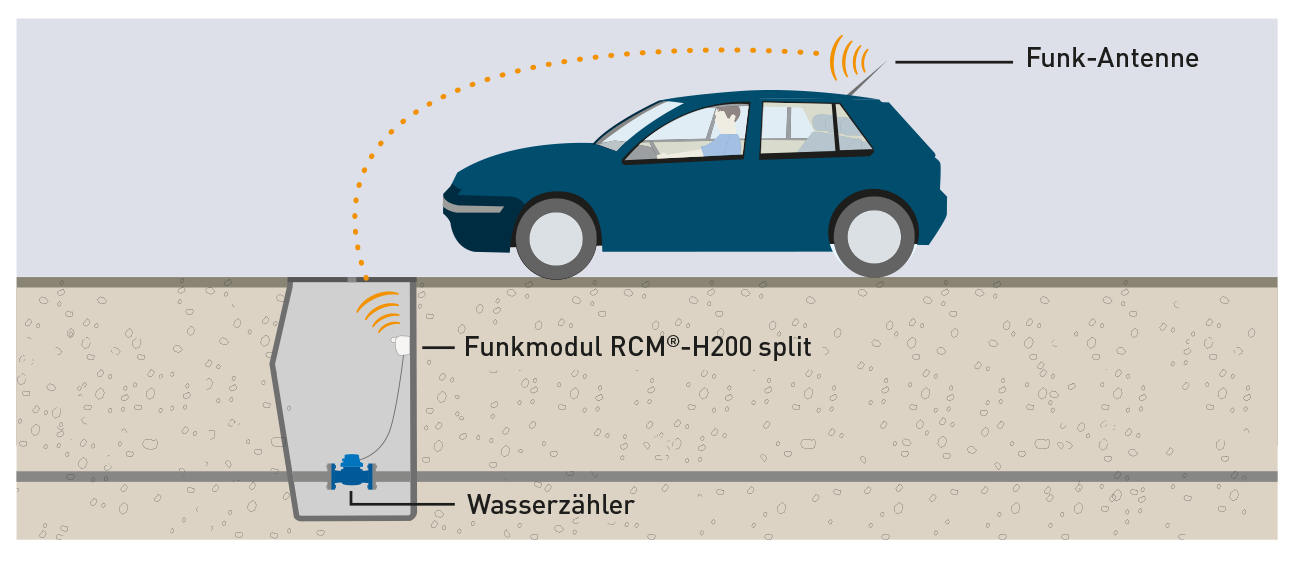
 - Funkmodul RCM®-H200 split
Dokumentation: RCM®-H200
Downloads
Properties
- Erreichung des grössten bekannten Messbereiches mit definiert kleinen Fehlergrenzen
- Horizontale Einbaulage
- Keine Einlaufstrecke notwendig
- Maximaler Betriebsdruck PN 16 bar
- Temperatur bis 50 °C
- Hydrodynamische Flügelbalance des Hauptzählers
- Optimaler Korrosionsschutz durch Pulverbeschichtung
- Anlaufwert ca. 8 l/h
- Federbelastetes Umschaltventil mit geringem Druckverlust
- Minimaler Druck von 0,5 bar vor dem Zähler erforderlich
- SVGW-Zertifizierung
 Konformität nach Europäischer Messmitteldirective (MID)
- Überflutungssicheres Haupt- und Nebenzählwerk (IP68) mit Multiprotokoll-Schnittstelle (MP), 5 m Kabel sowie je einer Aufnahme eines HRI Impulsgebers
- M-Bus Standardlast: 2 Lasten (3 mA)
Product information
Technische Daten
| Herstellerangaben | |||
|---|---|---|---|
| Nennweite | DN | mm | 150 |
| Nennweite Nebenzähler | DN | mm | 40 |
| Nenndruck | PN | bar | 16 |
| Zulässige Dauerbelastung | Q3 | m3/h | 400 |
| Maximale Belastung (1 x 24 h) | Q4 | m3/h | 600 |
| Trenngrenze ± 2 % | Q2 | m3/h | 0,15 |
| Untere Messbereichsgrenze ± 5 % | Q1 | m3/h | 0,035 |
| Umschaltung bei steigendem Durchfluss | m3/h | 8,3 | |
| Umschaltung bei fallendem Durchfluss | m3/h | 4,7 | |
| Temperatur | max.°C | 50 | |
| Masse und Gewichte | |||
|---|---|---|---|
| Baulänge | L | mm | 500 |
| Höhe | H | mm | 214 |
| Höhe | h | mm | 135 |
| Ausbauhöhe Messeinsatz | g | mm | 393 |
| Breite | B | mm | 275 |
| Breite | b | mm | 145 |
| Gewicht Zähler | ca. kg | 60 | |
| MID-Zulassungsdaten | |||
|---|---|---|---|
| Zulässige Dauerbelastung | Q3 | m3/h | 250 |
| Temperatur | max.°C | 30 | |
| Messbereich | R2500 | ||
Massbilder

Werkstoffe
| Gehäuse Hauptzähler | Grauguss |
| Gehäuse Nebenzähler | Messing |
| Messeinsatz | Kunststoff |
| Messflügel | Kunststoff |
| Federumschaltventil | Kunststoff / Nichtrostender Stahl |
Messfehlerkurve

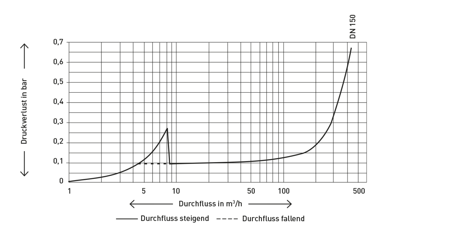
Druckverlustkurve
Einbaulagen
| Rohrleitung: | waagrecht | |
| Kopf des Zählers: | nach oben |
Inbetriebnahme-Hinweis
Bei Inbetriebnahme zwingend langsames Füllen der Leitungen mit Wasser (langsames Entlüften) beachten.
Zifferblätter
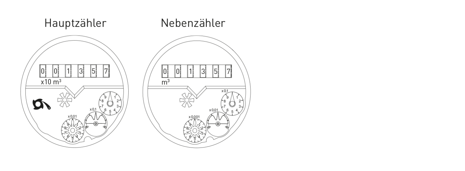
| Nennweite | DN | 150 |
| Kleinster Skalenwert Nebenzähler | m3 | 0,0005 |
| Registrierfähigkeit Hauptzähler | m3 | 10'000'000 |
Bestellangabe
| Durchflussrichtung | Position des Nebenzählers... |
|---|---|
| links-rechts | ...in Fliessrichtung rechts |
| rechts-links | ...in Fliessrichtung links |
Impulswertigkeit HRI Impulsgeber
| Zählergrösse | DN 150 1 Impuls = ...Liter |
|---|---|
| WPV-MS-Hauptzähler | 1000 10000 |
| WPV-MS-Nebenzähler | 100 1000 |
GWFcoder®-Technologie
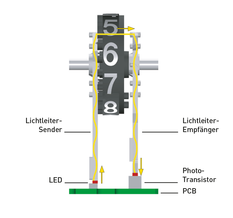
Beim GWFcoder®-System werden die einzelnen Rollen des mechanischen Zählwerkes opto-elektronisch abgegriffen. Die unterschiedlich langen, asymmetrisch angeordneten Schlitze in den Zahlrollen werden mit fünf Lichtschranken (Lichtleiter-Sender und -Empfänger) auf ihre Stellung abgetastet. Die Lichtschranken sind mit Phototransistoren, LEDs und Lichtleitern realisiert, die alle nacheinander gescannt und ausgewertet werden. Die exakt definierte Position jeder einzelnen Zahlenrolle wird als Absolut-Zahlenrollenstand codiert und als Bestandteil des Protokolls über die GWFcoder®-Schnittstelle ausgelesen. Dieses Funktionsprinzip ist von GWF patentiert. Die GWFcoder®-Schnittstelle hat im Vergleich zu einem Zähler mit Impulsausgang einen unvergleichbar höheren Informationsgehalt und erhöht die Auslesesicherheit. Ein GWFcoder®-Zählwerk benötigt keine Batterie, wodurch bestehende Revisionszyklen nicht beeinträchtigt werden. Die Energie für die Auslesung liefert das Auslesegerät.
Zusätzlich bieten die Produkte mit Zusatz «MP» (Multiprotokoll) die Flexibilität, zwischen Wandablesung (Induktiv oder CL), Wired M-Bus oder Funkauslesung zu wählen und das System per «Plug & Play» unbeschwert und schnell in Betrieb zu nehmen.
GWFcoder®-Datensatz
| Medium | Wasser |
| Absolut-Zählwerkstand | 1236547 m3 |
| Seriennummer | 43215678 |
| Zähler-Grösse | DN 150 |
M-Bus: EN 13757 --> Kabelfarben schwarz / rot, polaritätsunabhängig
ECO: EN 13757-3 --> Kabelfarben schwarz / grün / rot, Polarität beachten!
Anwendungsbeispiel
Funkauslesung
Zähler mit GWFcoder®-Zählwerk wird mittels mobiler Infrastruktur (z. B. RCM®-H200 Funkmodul und MEx) automatisiert ausgelesen.