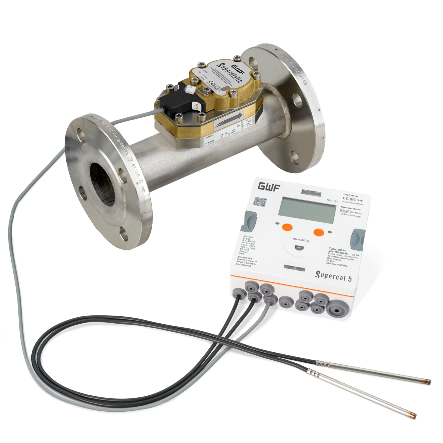
Static Heat- and Cooling Meter
Supercal 5S
Categorías de productos
This new serie is characterised by state-of-the-art multi-functional technologies, is based on a user-friendly modular concept and fully meets customer specific needs as simplified system integration, tariff and data logger functions, universal data transfer and connection to system processors.
Calefacción / Refrigeración
Ultrasónico
Cableado
Impulse,
M-Bus,
Modbus,
BacNET
Smart Building
Sus ventajas
- Fluid oscillation principle:
High stability and repeatability for a longterm and accurate measurement, even with poor water quality - No moving parts:
Not sensitive to dirt, air bubbles and liquids with changing viscosity - No straight section necessary up to DN40 and only 3 DN necessary for DN50 and up:
High flexibility in building planning - Rugged and durable calculator:
Particularly rugged construction of the casing and the mechanical and electrical connections - NFC Interface:
For a simplified and user-friendly calculator configuration on site
Aplicaciones
- High-end device for building management
- All applications in district heating and cooling or building automation
- Optimally suited for glycol and other mixtures
- As a replacement for mechanical impeller heat meters
Opciones
- Up to 2 option cards can be retrofitted, either Ex-Factory or on site, or replaced at any time without affecting the approval of the calculator:
- M-Bus according to EN 13757
- BACnet MS/TP (RS485) / Modbus (RS485) – requires mains supply
- 2 Analogue outputs, 0-20 mA, 4-20 mA, 0(2)-10 V DC – requires mains supply
Características
- Exchangeable measuring head
- Common spare parts from qp 1 up to 1500 m3/h
- Complete range of pipes qp 1 - 1500 m3/h
- Dynamic flow range:
1 : 100 at qp 1 - 25 m3/h
1 : 50 at qp 40 - 400 m3/h
1 : 25 at qp 800 - 1500 m3/h - Protection class of flow sensor IP68
- For horizontal, up- and downstream pipes, threaded and flange fittings
- Direct pick-up of voltage pulses without reflectors
- Self-cleaning effect due to the fluid oscillating characteristic
- Corrosion resistant materials without moving parts (no wear)
- Temperature sensor Pt 500 (2- or 4-wires)
- Exchangeable calculator electronics while wiring remains in place
- Large, illuminated dot-matrix display (128 x 64 pixel)
- Freely configurable tariff and data logger functions (up to 2’175 entries)
- Battery (12+1-year) or mains powered for increased flexibility
- Integrated backup battery for metrological part
- Standard EN 1434 class 2
 Conformity according European Measuring Instruments Directive (MID) or Conformity according to the Directive Measurement Canada
Product information
Technical Data
| Volume measuring meter | Threaded connection, G ¾’’ - G 2” (DN 15 - 40) | |||||||||
|---|---|---|---|---|---|---|---|---|---|---|
| Nominal diameter | DN | mm | 15 | 20 | 15 | 20 | 25 | 40 | ||
| Operating pressure | PN | bar | 16 or 25 | |||||||
| Connection thread on meter | G…A | Inch | ¾ | 1 | ¾ | 1 | 1¼ | 2 | ||
| Connection thread on coupling | R… | Inch | ½ | ¾ | ½ | ¾ | 1 | 1½ | ||
| Nominal flow rate | qp | m3/h | 1 | 1.5 | 2.5 | 3.5 | 6 | 10 | ||
| Maximum flow rate | qs | m3/h | 2 | 3 | 5 | 7 | 12 | 20 | ||
| Minimum flow rate | qi | l/h | 10 | 15 | 25 | 35 | 60 | 100 | ||
| Low flow threshold value | l/h | 4 | 10 | 15 | 30 | 50 | ||||
| Kvs value | m3/h | 2.09 | 2.06 | 5.44 | 5.21 | 7.46 | 13.4 | 20.9 | ||
| Pressure loss at qp | bar | 0.20 | 0.25 | 0.09 | 0.25 | 0.16 | 0.25 | |||
| Maximum temperature | °C | 130 | ||||||||
| Standard measuring range | qi/qp | 1:100 | ||||||||
| Material | Brass | |||||||||
| Standard | EN ISO 228-1 | |||||||||
| Dimensions | ||||||||||
|---|---|---|---|---|---|---|---|---|---|---|
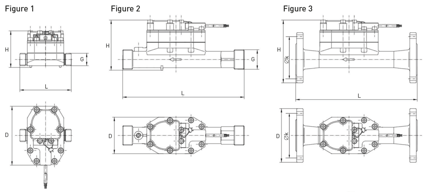
| Length without couplings | L | mm | 110 | 190 | 110 | 190 | 260 | 300 | ||
| Total height | H | mm | 79 | 105 | 122 | |||||
| Meter depth | D | mm | 125 | 78 | ||||||
| Meter weight | kg | 2.9 | 3.2 | 2.9 | 3.2 | 3.5 | 4.5 | |||
| Figure Number | 1 | 2 | ||||||||
| Volume measuring meter | ANSI-Flanged connection, NPS 2 - NPS 8 | ||||||||
|---|---|---|---|---|---|---|---|---|---|
| Nominal pipe size | NPS | inch | 2 | 2½ | 3 | 4 | 5 | 6 | 8 |
| Class | 150 | ||||||||
| Nominal flow rate | qp | m3/h | 15 | 25 | 40 | 60 | 100 | 150 | 250 |
| Maximum flow rate | qs | m3/h | 30 | 50 | 80 | 120 | 200 | 300 | 500 |
| Minimum flow rate | qi | l/h | 150 | 250 | 800 | 1200 | 2000 | 3000 | 5000 |
| Low flow threshold value | l/h | 75 | 125 | 400 | 600 | 1000 | 1500 | 2500 | |
| Kvs value | m3/h | 31.6 | 51.8 | 142 | 210 | 343 | 514 | 857 | |
| Pressure loss at qp | bar | 0.25 | 0.09 | 0.10 | |||||
| Maximum temperature | °C | 130 | |||||||
| Standard measuring range | qi/qp | 1:100 | 1:50 | ||||||
| Material | Spheroidal cast iron | Stainless steel | |||||||
| Standard | ASME B16.42-2016 | ASME B16.5-2003 | |||||||
| Dimensions | |||||||||
|---|---|---|---|---|---|---|---|---|---|
| Length | L | mm | 270 | 300 | 360 | 250 | 300 | 350 | |
| Total height | H | mm | 167 | 190 | 210 | 233 | 258 | 283 | NA |
| Meter depth | D | mm | 150 | 180 | 190 | 230 | 255 | 280 | 298.5 |
| Øk | Øk | mm | 120.7 | 139.7 | 152.4 | 190.5 | 215.9 | 241.3 | 298.5 |
| Bolts | 4 | 8 | |||||||
| Meter weight | kg | 9.8 | NA | 15.7 | 17.1 | 17.4 | 27.6 | NA | |
| Figure Number | 3 | ||||||||
| Volume measuring meter | DIN-Flanged connection, DN25 - 150, Material: Brass or Spheroidal cast iron | ||||||||||
|---|---|---|---|---|---|---|---|---|---|---|---|
| Nominal diameter | NPS | mm | 25 | 25 | 40 | 50 | 65 | 80 | 100 | 125 | 150 |
| Operating pressure | PN | bar | 16 or 25 | 16 | |||||||
| Nominal flow rate | qp | m3/h | 3.5 | 6 | 10 | 15 | 25 | 40 | 60 | 100 | 150 |
| Maximum flow rate | qs | m3/h | 7 | 12 | 20 | 30 | 50 | 80 | 120 | 200 | 300 |
| Minimum flow rate | qi | l/h | 35 | 60 | 100 | 150 | 250 | 800 | 1200 | 2000 | 3000 |
| Low flow threshold value | l/h | 15 | 30 | 50 | 75 | 125 | 400 | 600 | 1000 | 1500 | |
| Kvs value | m3/h | 7.46 | 13.4 | 20.9 | 31.6 | 51.8 | 142 | 210 | 343 | 514 | |
| Pressure loss at qp | bar | 0.16 | 0.25 | 0.09 | 0.1 | ||||||
| Maximum temperature | °C | 130 | |||||||||
| Standard measuring range | qi/qp | 1:100 | 1:50 | ||||||||
| Material | Brass | Spheroidal cast iron | |||||||||
| Standard | DIN-EN 1092-1 / DIN 2501 / ISO 7005-3 | DIN-EN 1092-1 / DIN 2501 / ISO 7005-1 | |||||||||
| Dimensions | |||||||||||
|---|---|---|---|---|---|---|---|---|---|---|---|
| Length | L | mm | 260 | 300 | 270 | 300 | 360 | 250 | 300 | ||
| Total height | H | mm | 134 | 157 | 171 | 189 | 203 | 226 | 254 | 286 | |
| Meter depth | D | mm | 115 | 150 | 165 | 185 | 200 | 220 | 250 | 285 | |
| Øk | Øk | mm | 85 | 110 | 125 | 145 | 160 | 180 | 210 | 240 | |
| Bolts | 4 (M12) | 4 (M16) | 8 (M16) | 8 (M20) | |||||||
| Meter weight | kg | 5.4 | 8.1 | 9.1 | 11.2 | 13.1 | 19 | 16 | 27.2 | ||
| Figure Number | 3 | ||||||||||

Dimension Diagram
Typical Head Loss Curve

Calculator
| Calculator | |
|---|---|
| Dimensions (HxWxD) | 162 x 143 x 54 mm |
| Environment class C | E1/M1 |
| Temperature sensor type | 2- or 4-wire, Pt 500 |
| Absolute temperature range | -20 °C to 200 °C |
| Approved temperature range | 1 °C to 200 °C |
| Absolute temperature difference | 1 K to 150 K |
| Homologation temperature difference | 3 K to 150 K |
| Response limit | 0.2 K |
| Temperature resolution t (display) | 0.1 °C |
| Temperature resolution Δt (display) | 0.01 K |
| Measurement accuracy | Better than requirements according to EN1434-1 |
| Measuring cycle temperature measurement - Battery operated (D-cell) - Mains operated | 10 s to 30 s (depends on flow rate) 3 s to 30 s (depends on flow rate) |
| Ambient temperature in operation | 5 °C to 55 °C |
| Transport and storage temperature | -20 °C to 70 °C (dry environment) |
| Ambient humidity | <93% relative humidity |
| Display | Illuminated (if mains powered) dotmatrix display (128 x 64 pixel) |
| Display units | 9 digits, MWh, m3, °C, K |
| Additional pulse inputs | Energy or volume |
| Protection class | IP65 in accordance to IEC 60529 |
| Power supply options | Battery D-cell (12+1-year lifetime) OR Mains, 100-240 V AC, 50/60 Hz OR Mains, 12-42 V DC or 12-36 V AC |
| 2 additional pulse inputs | Max. 200 Hz, 0-30 V DC |
| 2 open collector pulse outputs | Max. 200 Hz, 0-30 V DC |
| Optical Interface | According to IEC 62056-21:2002 |
| NFC Interface | According to ISO/IEC 14443 Type A |
| M-Bus Interface | According to EN 13757-2/3 Baudrate: 300 to 9’600 Bit/s 1 M-Bus standard unit load (1,5 mA) |
Temperature sensor
| Sensor element | Pt 500 |
| Connection diagram | 2- or 4-wire |
| Installation length | Depends on meter size |
Flow sensor
| Approved temperature range | 5 °C to 130 °C |
| Environment temperature | 5 °C to 55 °C |
| Storage temperature | -25 °C to 70 °C |
| Protection class | IP68 |
Installation
| Pipeline: | horizontal | |
| vertical | ||
| Meter head (for horizontal installation): | +/- 45° |
The principle of fluid oscillator flow sensor
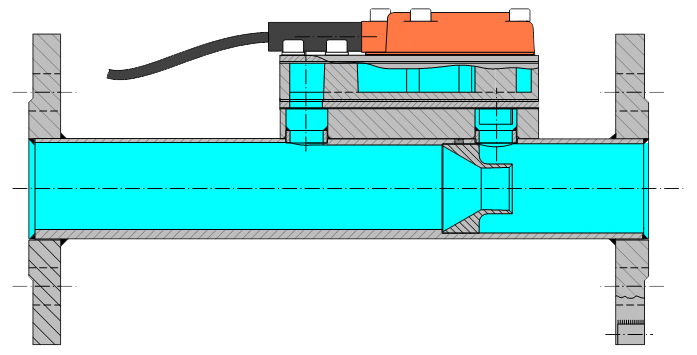
The main part of the flow passes through a Venturi nozzle in the pipe, creating the differential pressure to bypass the other part of the flow through the fluid oscillator.
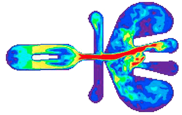
In the oscillator the liquid is led to a nozzle and accelerated to a jet. Opposite of the nozzle the jet is redirected to the left or right into a channel that leads upwards to the sensor head equipped with a piezo sensor. The pressure of the liquid on the sensor creates an electrical pulse. The liquid flows back to the pipe through a return loop and redirects the jet into the other channel where the action is repeated and fluid oscillation is created. The frequency of this oscillation is linear proportional to the volume flow. A supplementary benefit is the self cleaning effect due to the oscillating character.
The animated top view on the oscillator shows the differences of velocity of the liquid. The jet accelerated by the nozzle with the highest velocity in red, slow velocity in blue.