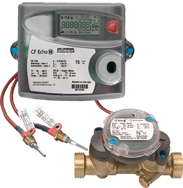
Ultrasonic combined heat and cooling meter
CF-Echo II
Product categories
Heat / Cooling
Ultrasonic combined heat and cooling meter
Heat / Cooling
Ultrasonic
Smart Building
Your benefits
- Ultrasonic technology:
Long-term stable energy measurement with maximum measuring accuracy - Patented warning signal processing:
Alarm message when soiled - Special lengths available for vertical impeller meters:
Simple replacement with ultrasonic technology possible - Option cards for various functions:
- Inexpensive basic device
- Subsequent functions can be implemented
Applications
- High-end device for building management
- As a replacement for mechanical impeller heat meters
- Metering of heat and/or cooling consumption in building management
Options
- Special version for combined heat/cold measurements (special programming)
- Calculator usable for compact mounting
- Option cards for:
- M-Bus / 2 water meter inputs
- M-Bus / 2 pulse outputs energy + volume
- M-Bus Power / 2 water meter inputs
- LonWorks, FTT-10A / 2 water meter inputs (separate supply 24 V AC/DC necessary)
- Modbus RTU (RS485) / 2 water meters inputs (Power supply module 230 V AC necessary) - Retrofittable external EquaScan - pMIU pulse radio module
Downloads
Electrical Scheme DN 15-50
Volume measuring meter CF-Echo US DN65-100 (german)
Installation and operating instruction CF-Echo II
CF-51/55 Calculator
Option card CF-Echo II (german)
Option card M-Bus Power CF-Echo II (german)
Option card LonWorks CF-Echo II (german)
EU DECLARATION OF CONFORMITY - CF Echo II
Properties
- Nominal diameters from DN 15 up to DN 50
- Nominal flow rates from qp 1,5 up to qp 15
- Lower pressure loss
- Universal installation position and no moving parts
- Operating temperature 130 °C, short term 150 °C
- Temperature sensor Pt 100 (2-wires)
- Electronic calculator and LCD-resolution 7 digits
- Non-volatile memory EEPROM and 24 month register
- Supply via 12-year battery, mains or M-Bus
- Maximum values with time stamp
- Standard EN 1434
 Conformity according European Measuring Instruments Directive (MID)
Product information
Technical Data
| Execution | CF-Echo II | |||||||||||||
|---|---|---|---|---|---|---|---|---|---|---|---|---|---|---|
| Nominal flow rate | qp | m3/h | 1,5 | 1,5 | 2,5 | 2,5 | 3,5 | 3,5 | 6 | 6 | 6 | 10 | 10 | 15 |
| Nominal diameter | DN | mm | 15 | 20 | 20 | 20 | 25 | 25 | 25 | 25 | 32 | 40 | 40 | 50 |
| Operating pressure | PN | bar | 16 | 16 | 16 | 16 | 16 | 16 | 16 | 16 | 16 | 16 | 16 | - |
| - | - | - | - | - | 25 | - | 25 | - | - | 25 | 25 | |||
| Kvs-value | m3/h | 3,21 | 3,21 | 6,01 | 6,01 | 10,41 | 10,41 | 16,39 | 16,39 | 16,39 | 33,15 | 33,15 | 33,8 | |
| Maximum flow rate | qs | m3/h | 3 | 3 | 5 | 5 | 7 | 7 | 12 | 12 | 12 | 20 | 20 | 30 |
| Minimum flow rate | qi | l/h | 15 | 15 | 25 | 25 | 35 | 35 | 60 | 60 | 60 | 100 | 100 | 150 |
| Starting flow | l/h | 3 | 3 | 5 | 5 | 7 | 7 | 12 | 12 | 12 | 20 | 20 | 30 | |
| Temperature | max. °C | 130 | 130 | 130 | 130 | 130 | 130 | 130 | 130 | 130 | 130 | 130 | 130 | |
| Short term temperature | max. °C | 150 | 150 | 150 | 150 | 150 | 150 | 150 | 150 | 150 | 150 | 150 | 150 | |
| Dimensions | CF-Echo II | |||||||||||||
|---|---|---|---|---|---|---|---|---|---|---|---|---|---|---|
| Length | L | mm | 110 | 130 | 130 | 190 | 150 | 260 | 150 | 260 | 260 | 200 | 300 | 270 |
| Height | A | mm | 72 | 72 | 72 | 72 | 77 | 77 | 77 | 77 | 77 | 85 | 85 | 77 |
| Height | B | mm | 18 | 18 | 18 | 18 | 23 | 23 | 23 | 23 | 23 | 35 | 35 | 35 |
| Flange external dimension | D | mm | - | - | - | 105 | - | 115 | - | 115 | - | - | 150 | 165 |
| Connection thread on meter | G…B | Zoll | ¾ | 1 | 1 | 1 | 1¼ | 1¼ | 1¼ | 1¼ | 1½ | 2 | 2 | - |
| Flange | - | - | - | X | - | X | - | X | - | - | X | X | ||
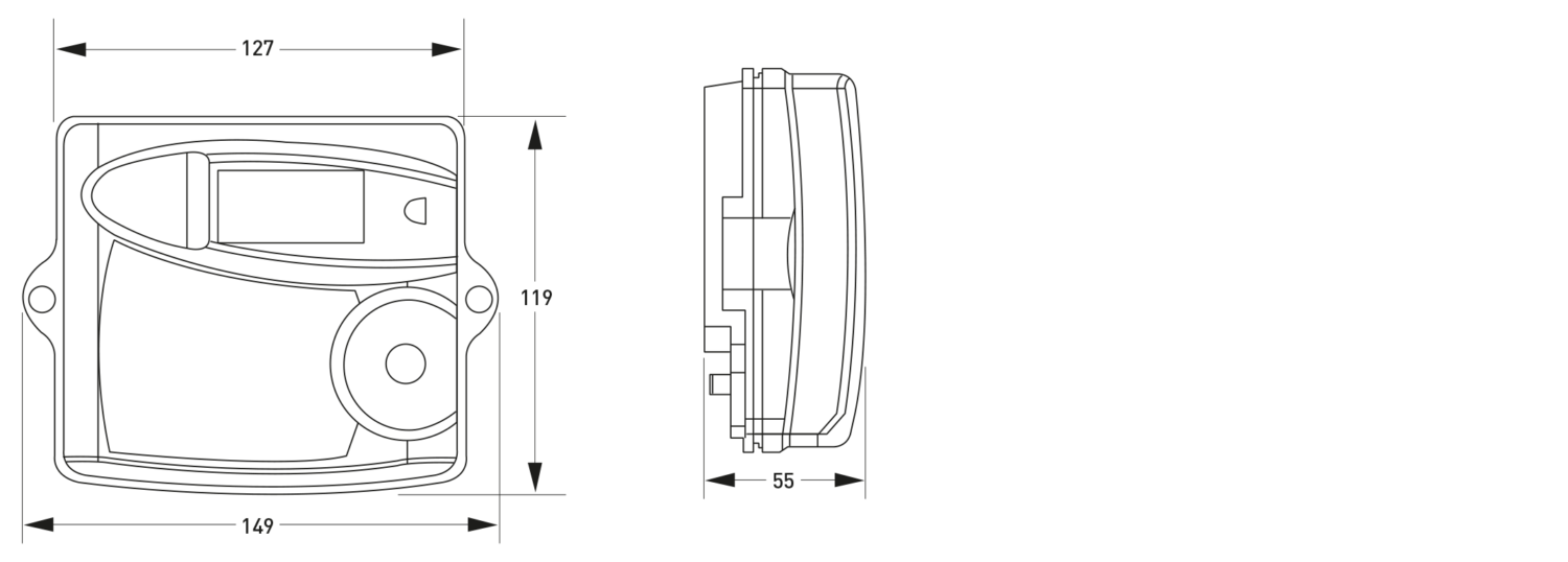
Dimension Diagram Calculator
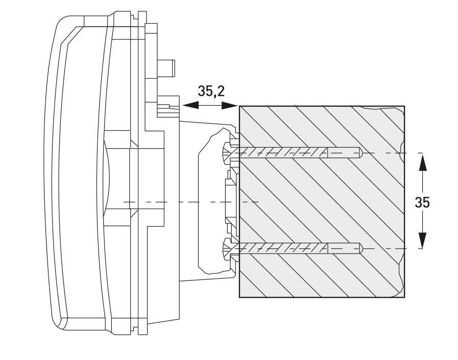
Wall-fastening
Dimension Diagram Flow Sensor

Soiling warning
The CF-Echo II processes a high signal level in a patented process to output a warning signal for the degree of soiling.

Technical Data Calculator / Temperature sensor / Volume measuring meter
| Calculator | |
|---|---|
| Temperature measuring range | 0 to180 °C |
| Temperature difference | 3 to160 K |
| Max. display resolution (7-digits) | 9'999,999 / 99'999,99 / 999'999,9 / 9'999'999 |
| Supply voltage lithium battery | 3,6 V |
| Battery lifetime | 12 years (optional mains or M-Bus) |
| Environment class | EN 1434 – class C |
| Protection class | IP54 |
| Environment temperature | +5 to +55 °C |
| Storage temperature | -10 to +60 °C |
| Optical interface | EN 60870-5, M-Bus protocol |
| Temperature sensor connection | 2-wires, cable Ø3,5 to 6,5 mm |
| Temperature sensor | |
|---|---|
| Sensor element | Pt 100 |
| Execution | Direct immersion sensor up to DN 20 Pocket sensor initiating DN 25 |
| Connection diagram | 2-wires |
| Installation length | 50 mm/105 mm qp 15 |
| Cable lengths | 2x1,75 m / 2x3,0 m initiating qp 15 |
| Volume measuring meter | |
|---|---|
| Metrological class approval acc. PTB | EN 1434 - class 2 / 1:100 |
| Calibration in class | 3 / 1:100 |
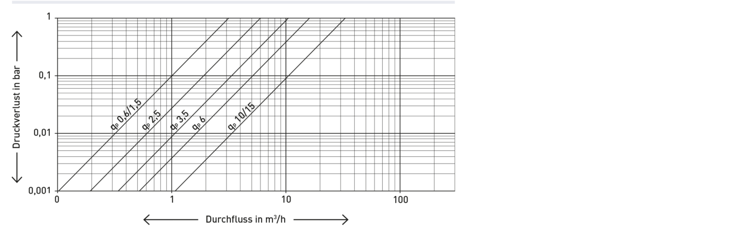
Typical Head Loss Curve
Option cards
As standard, CF-Echo II can accept various option cards. These option cards can also be connected to previously installed heat meters at a later date. The following option cards are available:
- M-Bus / 2 water meter inputs
- M-Bus / 2 pulse outputs energy + volume
- M-Bus Power / 2 water meter inputs
- LonWorks / 2 water meter inputs

Technical data on request
Multi-function display CF Echo II/CF-51/CF-55
Reading errors are minimised by the concise layout on 3 display levels and the clear symbols for status and alarm messages. The various display levels are selected via a red button. Press the button for app. 3 s to access the next level.
