
Ultraschall-Volumenmessteil
ULTRAFLOW® 44
Categorías de productos
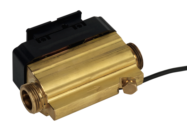
ULTRAFLOW® 44 ist ein statischer Durchflusssensor, der auf dem Ultraschallmessprinzip basiert. Er wird primär als Baugruppe in einem Wärmemengenzähler in Kombination mit den separaten Zählern MULTICAL® 603 oder MULTICAL® 803 und einem Satz Temperatursensoren eingesetzt. ULTRAFLOW® 44 wurde mit besonderem Augenmerk auf Wasserdichtigkeit (IP68) entwickelt und übersteht sogar kurzzeitiges Untertauchen (bis zu 2 Monate). Dadurch eignet sich ULTRAFLOW® 44 besonders für Fernwärme-/Fernkälteanwendungen (Hauptzähler, Umspannwerke etc.) bei Abrechnungsvorgängen und kann in Kälte- oder Wärme-/Kälteanlagen eingesetzt werden.
Calefacción / Refrigeración
Ultrasónico
Smart City
Smart Building
Sus ventajas
- Langlebiges, verschleissfreies Ultraschall-Volumenmessteil:
Hohe Messstabilität und Betriebssicherheit - Kompaktes Design:
Geringer Einbauplatz vor Ort erforderlich - Hohe Auflösung der Impulswertigkeit:
Präzise Momentanwerte - CH-Kältezulassung (METAS) inkl. Ersteichung:
Für den Einsatz im Verrechnungsverkehr zugelassen
Aplicaciones
- Speziell geeignet für Fernwärme/-kälte-Anwendungen (Hauptzähler, Übergabestationen usw.) im Verrechnungsverkehr
- Ersatz von mechanischen Flügelrad-Wärmezählern
- Wärme-/Kälte oder reine Kälte-Verbrauchsmessung im Gebäudetechnikbereich
- Ausschliesslich mit Rechenwerken der Baureihe MULTICAL® einsetzbar
Opciones
- Pulse Transmitter mit eigener Energieversorgung bei Kabellängen > 10 m
Características
- Nennweiten:
- Wärme/Kälte kombiniert: DN 15 bis DN 125
- Kälte: DN 15 bis DN 125 - Nenndurchflüsse qp 1,5 bis qp 100
- Niedriger Druckverlust
- Keine beweglichen Teile
- Signalübertragung zum Rechenwerk und Energieversorgung des Volumenmessteiles mittels 3-adrigem Kabel
- Mediumtemperatur 2 bis 130 °C (ab 90 °C wird ein Flanschzähler sowie die Absetzung des Rechenwerkes empfohlen)
- Bauartprüfung/Zulassung:
- Wärme: Konformität nach Europäischer Messmitteldirective (MID)
- Kälte: CH-Zulassung (METAS) inkl. Ersteichung
Product information
Technische Daten ULTRAFLOW® 44 (DN 15-50)
| ULTRAFLOW® 44 Series (DN 15-50) | ||||||||||||
|---|---|---|---|---|---|---|---|---|---|---|---|---|
| Nominal flow rate | qp | m3/h | 1,5 | 1,5 | 2,5 | 3,5 | 6 | 6 | 6 | 10 | 10 | 15 |
| Nominal diameter | DN | mm | 15 | 20 | 20 | 25 | 25 | 25 | 32 | 40 | 40 | 50 |
| Connection thread on the meter | G...B | Inch | ¾ | 1 | 1 | 1¼ | 1¼ | flange | 1½ | 2 | flange | flange |
| Maximum flow rate | qs | m3/h | 3 | 3 | 5 | 7 | 12 | 12 | 12 | 20 | 20 | 30 |
| Minimum flow rate | qi | l/h | 15 | 15 | 25 | 35 | 60 | 60 | 60 | 100 | 100 | 150 |
| Starting value | l/h | 3 | 3 | 5 | 7 | 12 | 12 | 12 | 20 | 20 | 30 | |
| Kvs value 1) | m3/h | 4.9 | 4.9 | 8.2 | 13.4 | 24.5 | 24.5 | 24.5 | 40 | 40 | 40 | |
| Meter factor 2) | p/l | 100 | 100 | 60 | 50 | 25 | 25 | 25 | 15 | 15 | 10 | |
| Maximum pressure | PN | bar | 25 | |||||||||
| Standard measuring range | qp / qi | 1:100 | ||||||||||
| Protection class | IP68 | |||||||||||
1) q=kv x √∆p
2) The meter factor appears from the type label
| ULTRAFLOW® 44 Series (DN 25-125) | |||||||
|---|---|---|---|---|---|---|---|
| Nominal flow rate | qp | m3/h | 25 | 40 | 60 | 100 | 100 |
| Nominal diameter | DN | mm | 65 | 80 | 100 | 100 | 125 |
| Connection | flange | flange | flange | flange | flange | ||
| Maximum flow rate | qs | m3/h | 50 | 80 | 120 | 200 | 200 |
| Minimum flow rate | qi | m3/h | 0,25 | 0,4 | 0,6 | 1 | 1 |
| Starting value | l/h | 50 | 80 | 120 | 200 | 200 | |
| Kvs value 4) | m3/h | 102 | 179 | 373 | 373 | 373 | |
| Meter factor 3) | p/l | 6 | 5 | 2.5 | 1.5 | 1.5 | |
| Maximum pressure | PN | bar | 25 | ||||
| Maximum Temperature | °C | 130 | |||||
| Standard measuring range | qp / qi | 1:100 | |||||
3) q=kv x √∆p
4) The meter factor appears from the type label
Pressure loss
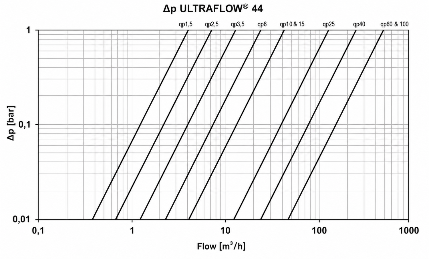
The pressure loss in a flow sensor is stated as the maximum pressure loss at qp.
According to EN 1434, the maximum pressure loss must not exceed 0,25 bar.
Mechanical data
| Ultraflow® 44 | |
|---|---|
| Accuracy class | 2 and 3 |
| Electromagnetic environment | Fulfils EN 1434 class C, MID E1 and E2 |
| Mechanical environment | MID M1 and M2 |
| Ambient conditions | 5...55 °C, closed location (installation indoors) |
| Protection class | IP68 |
| Medium in flow sensor | Water – recommended water quality as in CEN TR 16911 and AGFW FW510 |
| Medium temperature5) | 2...130 °C or narrower range |
| Storage temperature (empty sensor) | -25...60 °C |
| Pressure stage | PN16/PN25, PS25 see marking |
| Straight inlet requirement | 0D (according to EN 1434) |
| Installation angle | Horizontally, vertically and at an angle |
5) At medium temperatures above 90°C, the use of flange meters is recommended.
At medium temperatures above 90 °C or below the ambient temperature, the calculator and Pulse Transmitter/Pulse Divider must not be mounted on the flow sensor. Instead wall mounting is recommended.
| Materials | |
|---|---|
| Wetted parts: | |
| Housing, thread | DZR brass (dezincification-resistant brass) CW511L with max 0.1% Pb, implemented in 2024 |
| Blind plug | DZR brass (dezincification resistant brass) CW510L with max 0.1% Pb, implemented in 2024 |
| Housing, flange | Stainless steel, W.no. 1.4308 |
| Transducer (membrane) | Stainless steel, W.no. 1.4404 |
| O-ring | Ethylene propylene (EPDM) |
| Reflector base/reflector | Thermoplastic, PESU 30 % GF and stainless steel, similar to AISI 304 or AISI 316 (qp 0.6...2.5 m³/h) Thermoplastic, PESU 30 % GF and stainless steel, similar to AISI 304 (qp 6 and 10 m³/h) Stainless steel, similar to AISI 304 or AISI 316 - (qp 3.5, 15...100 m³/h) |
| Measuring tube | Thermoplastic, PESU – only flow sensor type 65-4-XXHX-XXX/Thermoplastic, PESU 30% GF |
| Electronic housing: | |
| PCB box | Thermoplastic, inside - polyolefin, outside - polyamide |
| Base (flow sensor) | qp 1.5 - 2.5 Thermoplastic, PESU 30% GF qp ≥ 3.5 Thermoplastic PC 10% GF |
| Cover (flow sensor) | Thermoplastic, PC 10% GF |
| Coaxial cable | Copper cable with silicone jacket and inner fluoropolymer insulation |
| Connection cable | Silicone cable (3 x 0.25 mm²) |
Approved meter data
| Ultraflow® 44 | |
|---|---|
| heat meter | DK-0200-MI004-044 EU-Type Examination Certificate DK-0200-MID-D-001 MID-certified according to Module D |
| cooling meter | TS 27.02 014 (DANAK accreditation 268) |
| Standards and norms | EN 1434:2007/AC2007 EN 1434:2015+A1:2015 EN 1434:2022 WELMEC 7.2:2021 |
| EU directives | Low Voltage Directive Electromagnetic Compatibility Directive Pressurised Equipment Directive (DN50...DN125 category I) |
| EN 1434 designation | Environmental class C Fast response meter |
| MID mechanical environment | Class M1 and M2 |
| MID electromagnetic environment | Class E1 and E2 |
| MID climatic environment | 5...55 °C, condensing, closed location (indoors) |
| MID accuracy class | 2 and 3 |
Accuracy
| Ultraflow® 44 | |
|---|---|
| Class 3 | Ef = ±(3 + 0.05 qp/q), but not above ±5% |
| Class 2 | Ef = ±(2 + 0.02 qp/q), but not above ±5% |
| Typical 6) | Ef = ±(1 + 0.01 qp/q) |
6) Documented with DANAK-accredited certificate at flow qi, 0.1 qp and qp.
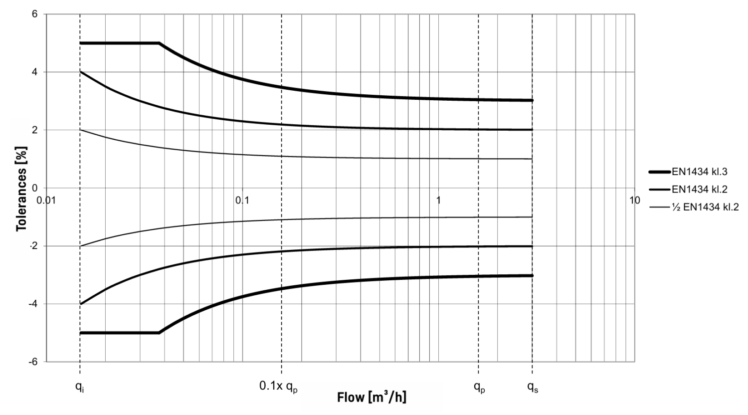
Flow sensor tolerances q¨p¨¨:q¨i¨¨ 100:1 (qp 1,5 m³/h)
Dimensioned sketches
All ULTRAFLOW® 44 flow sensors include a separate electronics box, which contains the PCB. This electronics box is connected to the plastic casing on the respective meter housing with a coaxial cable with a length of l < 1.2 m. The plastic casing on the meter housing contains the transducers of the flow sensor. Flow sensors of size qp 1.5...10 m³/h have the provision for built-in temperature sensors (M10x1 connection).
ULTRAFLOW® 44 - PCB and cables
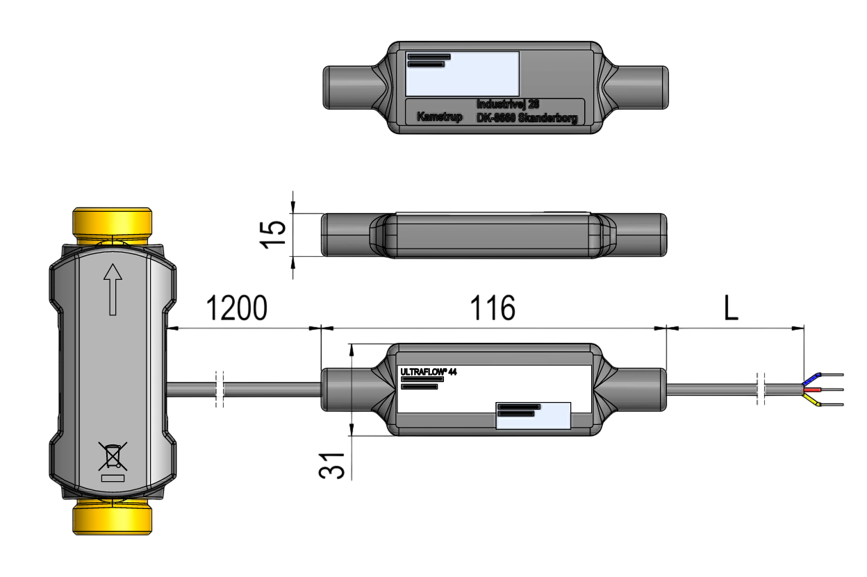
ULTRAFLOW® 44, G¾B und G1B
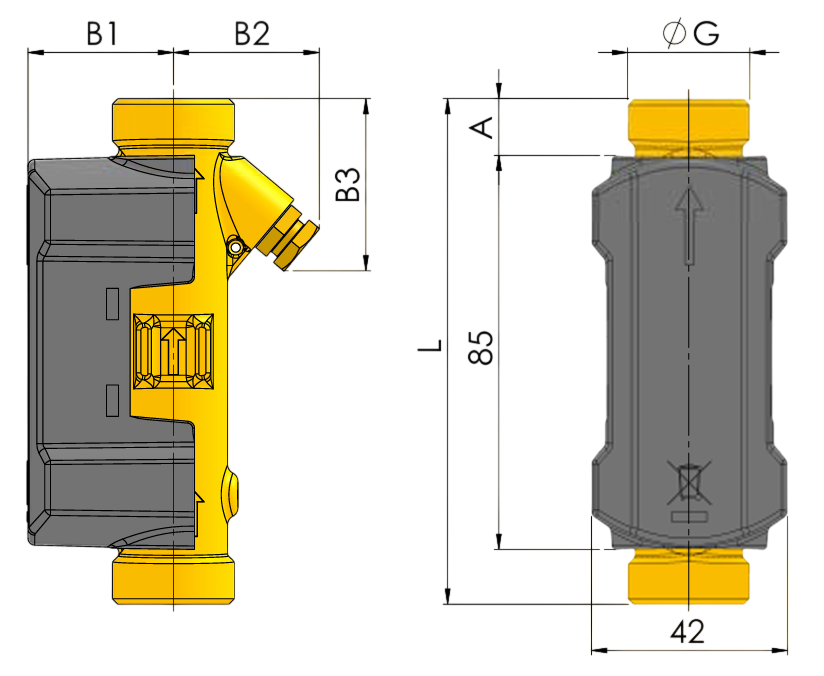
| ULTRAFLOW® 44, G¾B und G1B | |||||
|---|---|---|---|---|---|
| Nominal flow rate | qp | m3/h | 1,5 | 1,5 | 2,5 |
| Thread | G | Inch | G¾B | G1B | G1B |
| Total length | L | mm | 110 | 130 | 190 |
| Dimension A | A | mm | 12 | 22 | 52 |
| Dimension B1 | B1 | mm | 35 | 38 | 38 |
| Dimension B2 | B2 | mm | 32 | 32 | 38 |
| Dimension B3 | B3 | mm | 38 | 48 | 78 |
| Weight | app. kg | 0,6 | 0,7 | 0,9 | |
Including the electronics box and L = 2.5 m signal cable.
ULTRAFLOW® 44, G1¼B, G1½B and G2B
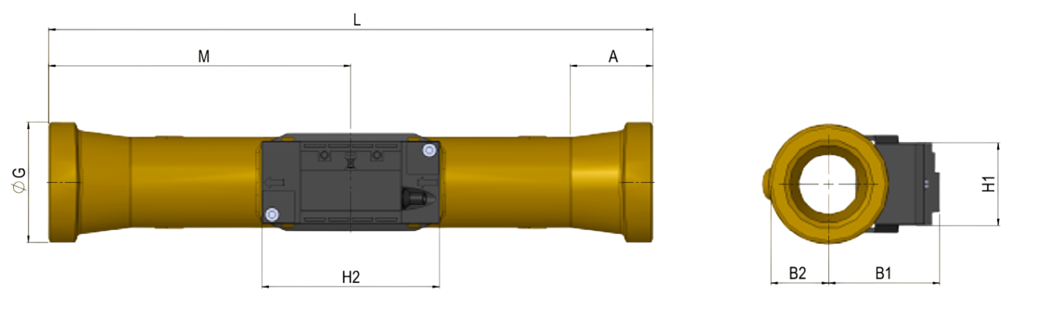
| ULTRAFLOW® 44, G1¼B, G1½B and G2B | ||||||
|---|---|---|---|---|---|---|
| Nominal flow rate | qp | m3/h | 3,5 | 6 | 6 | 10 |
| Thread | G | Inch | G1¼B | G1¼B | G1½B | G2B |
| Total length | L | mm | 260 | 260 | 260 | 300 |
| Dimension M | M | mm | L/2 | L/2 | L/2 | L/2 |
| Dimension H2 | H2 | mm | 88 | 88 | 88 | 88 |
| Dimension A | A | mm | 16 | 16 | 31 | 40.2 |
| Dimension B1 | B1 | mm | 51 | 53 | 60 | 55 |
| Dimension B2 | B2 | mm | 20 | 20 | 24 | 29 |
| Dimension H1 | H1 | mm | 41 | 41 | 41 | 41 |
| Weight | app. kg | 1.9 | 2.0 | 2.0 | 2.9 | |
Including the electronics box and 10 m signal cable.
ULTRAFLOW® 44, DN25, DN40 and DN50
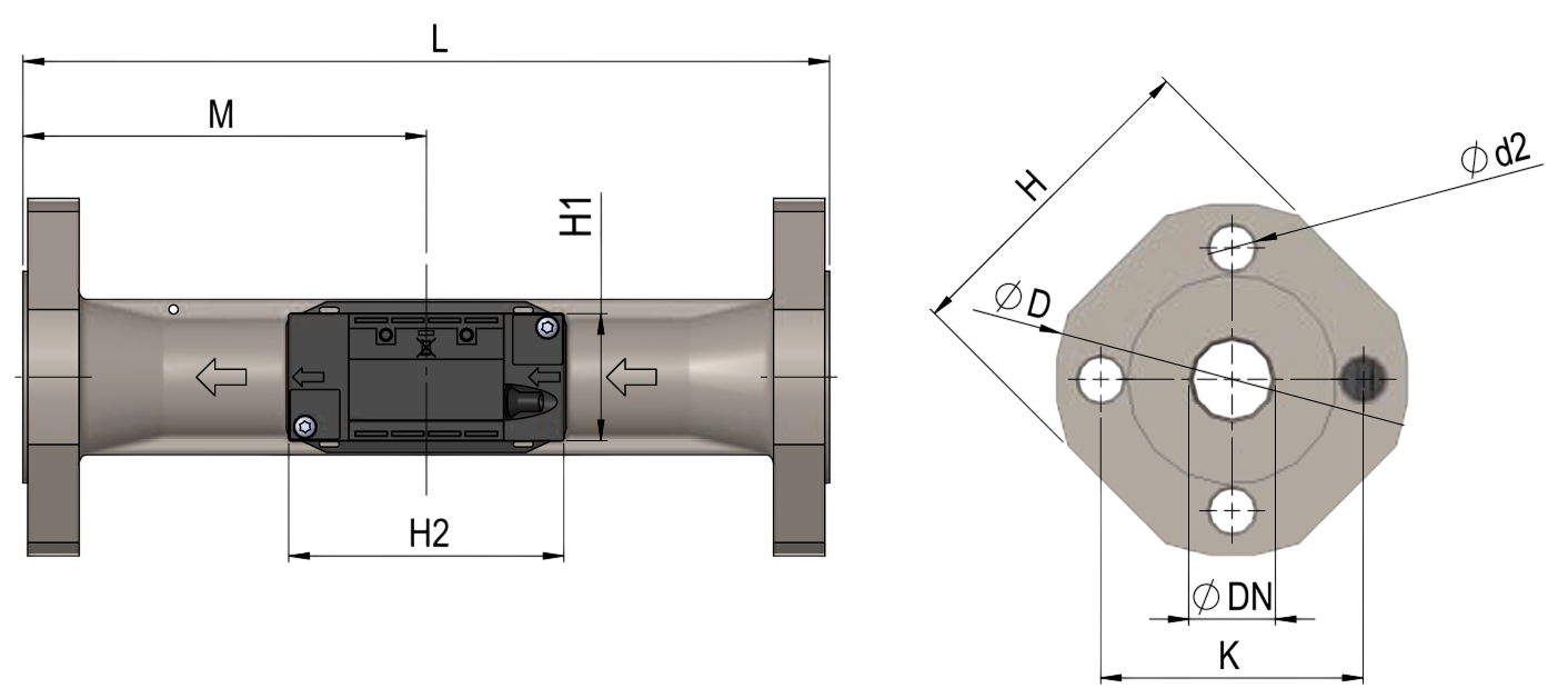
| ULTRAFLOW® 44, DN25, DN40 and DN50 | |||||
|---|---|---|---|---|---|
| Nominal flow rate | qp | m3/h | 6 | 10 | 15 |
| Diameter | mm | DN25 | DN40 | DN50 | |
| Total length | L | mm | 260 | 300 | 270 |
| Total height | H | mm | 106 | 140 | 145 |
| Dimension M | M | mm | L/2 | L/2 | 155 |
| Dimension H1 | H1 | mm | 41 | 41 | 41 |
| Dimension H2 | H2 | mm | 88 | 88 | 88 |
| Dimension D | D | mm | 115 | 150 | 165 |
| Dimension K | K | mm | 85 | 110 | 125 |
| Bolts d2 | d2 | mm | 14 | 18 | 18 |
| Bolts Thread | M12 | M16 | M16 | ||
| Weight | app. kg | 4.5 | 7.4 | 8.5 | |
Including the electronics box and 10 m signal cable.
ULTRAFLOW® 44, DN65 to DN125
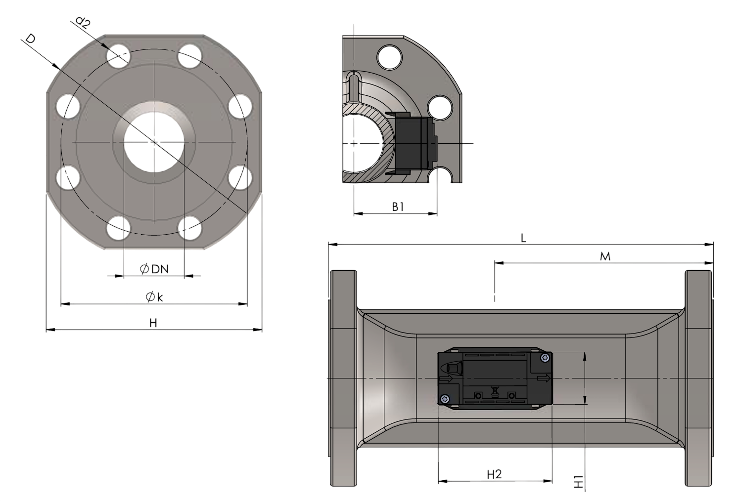
| ULTRAFLOW® 44, DN65 to DN125 | |||||||
|---|---|---|---|---|---|---|---|
| Nominal flow rate | qp | m3/h | 25 | 40 | 60 | 100 | 100 |
| Diameter | mm | DN65 | DN80 | DN100 | DN100 | DN125 | |
| Total length | L | mm | 300 | 300 | 360 | 360 | 350 |
| Total height | H | mm | 168 | 184 | 220 | 220 | 260 |
| Dimension M | M | mm | 170 | 170 | 210 | 210 | 212 |
| Dimension H1 | H1 | mm | 41 | 41 | 41 | 41 | 41 |
| Dimension H2 | H2 | mm | 88 | 88 | 88 | 88 | 88 |
| Dimension B1 | B1 | mm | |||||
| Dimension D | D | mm | 185 | 200 | 235 | 235 | 270 |
| Dimension k | k | mm | 145 | 160 | 190 | 190 | 220 |
| Bolts d2 | d2 | mm | 18 | 18 | 22 | 22 | 26 |
| Bolts Thread | M16 | M16 | M20 | M20 | M24 | ||
| Weight | app. kg | 13.5 | 17.1 | 22.0 | 22.0 | 28.5 | |
Including the electronics box and 10 m signal cable.
Einbau-Hinweis
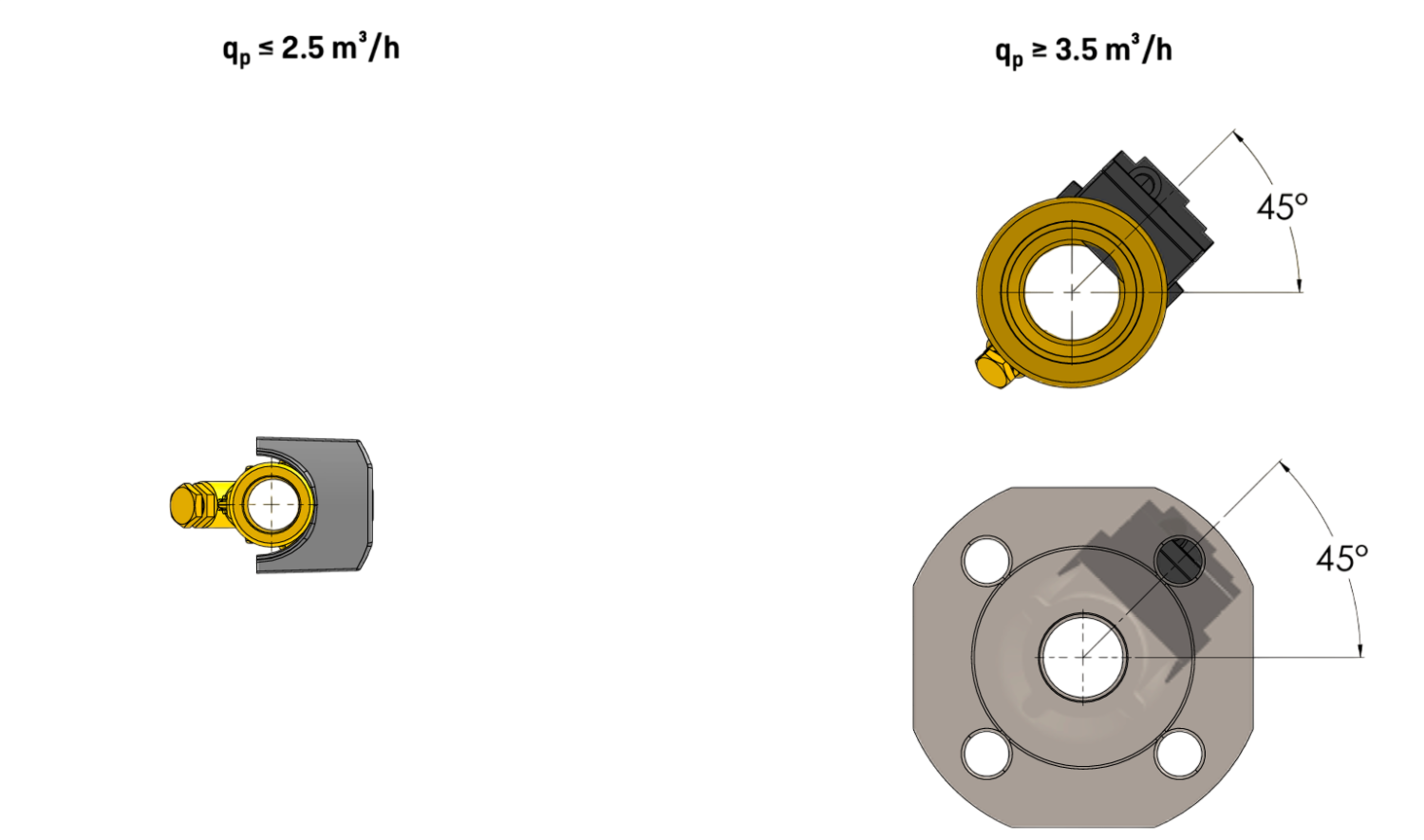
Bei ULTRAFLOW® 44 muss das schwarze Elektronikgehäuse an der Seite sitzend eingebaut werden (bei waagrechter Installation). ULTRAFLOW® 44 kann bis - 45° im Verhältnis zur Rohrachse gedreht werden. Bei Kondensationsgefahr, z. B. in Kälteinstallationen oder wenn ULTRAFLOW® 44 in feuchter Umgebung installiert wird, muss ULTRAFLOW® 44 - 45° zur Rohrachse gedreht werden. ULTRAFLOW® 44 erfordert weder eine gerade Einlauf- noch Auslaufstrecke. ULTRAFLOW® 44 darf keinem niedrigeren Druck als dem Umgebungsdruck (Vakuum) ausgesetzt sein.
Einbau-Empfehlungen
Kräftige Durchflussstörungen treten meist im Zusammenhang mit nicht vollständig geöffneten Ventilen und Pumpen sowie Mehrfachbögen auf. Die dazu unten aufgeführten minimalen Abstände haben sich bei der Installation von thermischen Energiezählern bewährt (Best-Practice-Ansatz):
| Minimal empfohlene Abstände | Ultraschall-Volumenmessteil DN 15 - 80 | Ultraschall-Volumenmessteil DN 100 - 250 |
|---|---|---|
| Bei nicht vollständig geöffneten Ventilen | 20 x DN | 40 x DN |
| Auf der Druckseite von Pumpen | 20 x DN | 20 x DN |
| Bei Mehrfachbögen | 5 x DN | 5 x DN |
Installation positions
| Pipeline: | horizontal |  |
| vertical |  | |
| diagonal |  | |
| Head of the meter | to the side |  |
| ULTRAFLOW® 44 DN 15 – DN 125: | - 45° |  |
Elektrische Verbindungen
| ULTRAFLOW® 44 | ||
|---|---|---|
| ULTRAFLOW® 44 | → | MULTICAL® |
| Blau (Masse) | → | 11 |
| Rot (Versorgung) | → | 9 |
| Gelb (Signal) | → | 10 |