
Calculator
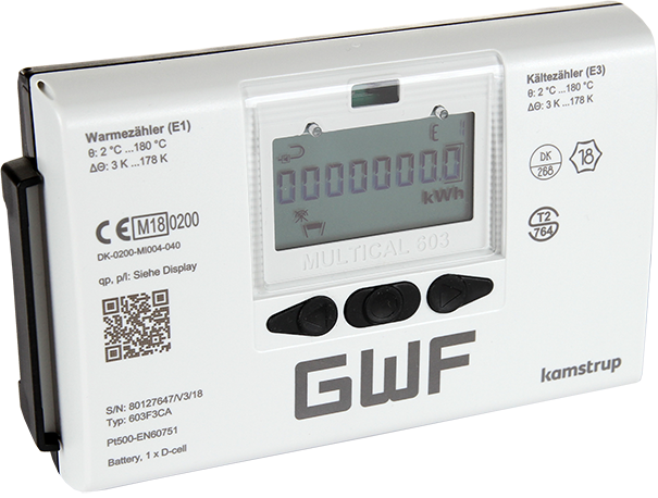
MULTICAL® 603
Kategorie produktowe
Ciepłomierze / Chłodomierze
The future-proof heat and cooling meter with complete flexibility next-generation Quality
Flexibility and scalability are key to ensuring that today's meter solution is well equipped to meet future challenges. The new MULTICAL® 603 with efficient dimensions comes in a modern design and is an all-round calculator. The heat meter, cooling meter or combined heat/cooling meter allows you to easily upgrade and replace your measuring devices. This means you are ready for new opportunities and challenges.
Ciepłomierze / Chłodomierze
Ultradźwiękowe
Technika systemowa
Z przewodem
Impulse,
M-Bus,
Modbus,
BacNET
Bezprzewodowe
wM-Bus,
LoRaWAN
Smart City
Smart Building
Korzyści
- Ultrasonic technology:
Long-term stable energy measurement with maximum measurement accuracy - Highly flexible modular design:
Expandable base unit, reduced inventory requirements - Auto detect function of ULTRAFLOW®:
One calculator for all flow sensor sizes - Comprehensive data logger:
Instant access to information for analysis and optimization purposes - One-time programming of metrological parameters on site without breaking the MID seal:
Flexibility and time savings during commissioning - Option cards for various functions:
- Affordable base unit
- Additional functions can be added later - CH refrigeration certification (METAS) incl. initial calibration:
Approved for use in commercial transactions
Zastosowanie
- Particularly suitable for district heating/cooling applications (main meters, transfer stations, etc.) in billing transactions
- Heat and/or cooling consumption measurement in building services engineering
- Calculator for local or remote reading
- Leakage and pipe break monitoring in district heating systems
Opcje
- Mixed fluid on version (603-M) on request
- Option cards for
- M-Bus / 2 water meter inputs
- M-Bus / 2 pulse outputs energy + volume
- Radio OMS T1, 868 MHz (battery life 11 years)
- 2 active analog outputs 0/4…20 mA (mains power supply required)
- LonWorks, TP/FT-10 / 2 water meter inputs (high-power power supply required)
- BACnet MS/TP (RS485) / 2 water meter inputs (mains power supply required)
- Modbus RTU (RS485) / 2 water meter inputs (mains power supply required)
- Modbus TCP-IP / 2 water meter inputs (high-power power supply required)
- BACnet IP / 2 water meter inputs (high-power power supply required)
- LoRaWAN int./ext. antenna
Pliki do pobrania
Installation instructions, Connection ULTRAFLOW® 54 (DE)
Electrical diagram MULTICAL® 603
Electrical diagram OPTIFLUX 4300W MULTICAL® UD
Electrical diagram OPTIFLUX 4300W MULTICAL® BD
Electrical diagram WATERFLUX 3300W MULTICAL® UD
Electrical diagram WATERFLUX 3300W MULTICAL® BD
Connection diagram for option cards
2026_EU Declaration of Conformity_MULTICAL_603
Cechy
- Large LCD display, resolution 7 or 8 digits
- Mains power supply 230 V AC, power supply 24 V AC / V DC or with 16-year battery for wall mounting
- Supported, integrated real-time clock (RTC) and data logger, mains power supply 230 V AC
- Pt 500 temperature sensor, 2-/4-wire technology (603-M 2-wire)
- Storage of the last 36 monthly and 20 annual values
- Can be combined with the following volume measuring parts:
- ULTRAFLOW®
- Impeller meter with reed pulse generator
- Magnetic-inductive meter - Type testing/approval:
- Heat: Conformity according to European Measuring Instruments Directive (MID)
- Cold: CH approval (METAS) incl. initial calibration
Product information
Mechanical design MULTICAL® 603
Mechanical data
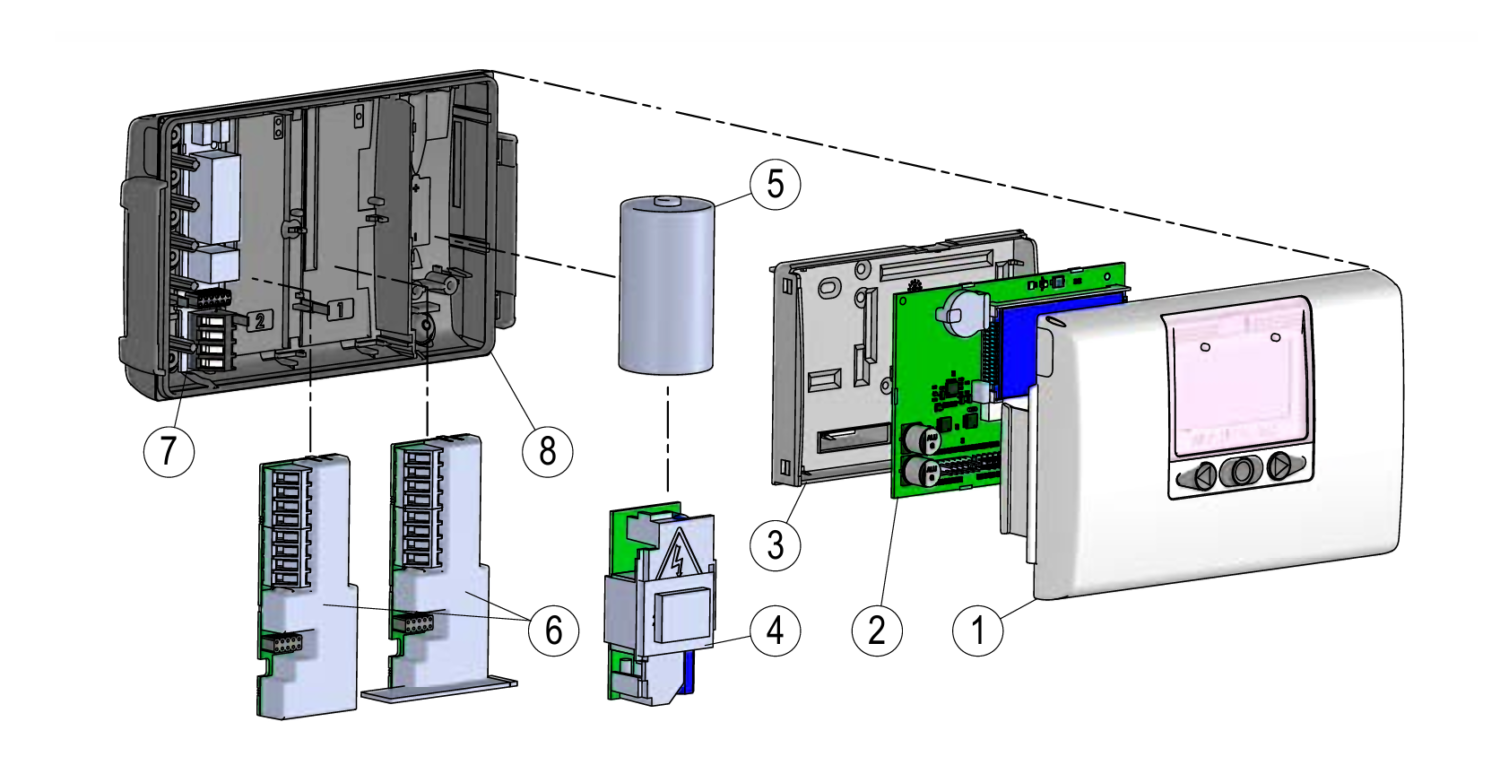
- Upper part of the calculator unit with front buttons and laser engraving
- Circuit board with microcontroller, display, etc.
- Calibration cover (Note: May only be opened by authorized testing laboratories)
- Either a power supply module can be installed…
- …or a battery can be installed
- 1 or 2 communication modules
- Connections for temperature sensors and flow sensors
- Lower part of the calculator unit
| MULTICAL® 603 | |
|---|---|
| Weight | 450 g |
| Ambient temperature | 5…55 °C, non-condensing, closed location (indoor installation) |
| Protection class | IP65 |
| Media temperatures in ULTRAFLOW® | 2…130 °C For media temperatures below ambient temperature or above 90 °C, wall mounting of the calculator is recommended. |
| Media in ULTRAFLOW® | Water (district heating water as described in CEN TR 16911 and AGFW FW510) MULTICAL® 603 is not approved for use with drinking water |
| Storage temperature | -25…60 °C (drained meter) |
| Connection cable | ø 3,5…6 mm |
| Supply cable | ø 5…8 mm |
| Materials | |
|---|---|
| Housing top and bottom | Thermoplastic, PC 10 % GF with TPE (thermoplastic elastomer) |
| Verification cover | ABS |
| Cables | Silicone cable with internal Teflon insulation |
| Gasket | TPE (thermoplastic elastomer) |
| Push buttons | TPE (thermoplastic elastomer) |
Approved meter data
| MULTICAL® 603 | |
|---|---|
| Heat meter | DK-0200-MI004-040 |
| Cooling meter | TS 27.02 012 |
| Bifunctional heat/cooling meter | Labeled with DK-0200-MI004-040 and TS 27.02 012 as well as year mark as MID |
| Temperature range | θ: 2 °C…180 °C |
| Differential range | ∆Θ: 3 K…178 K |
| Total temperature range | The specified minimum temperatures are only related to the type approval. The meter has no cut-off for low temperature and thus measures down to 0,01 °C and 0,01 K. |
| Mixed fluid meter | EN 1434 without MID approval |
| Temperature range | θ: -40 °C…140 °C |
| Differential range | ΔΘ: 3 K…180 K |
| Total temperature range | The temperature range -40 °C…140 °C indicates the technical operating range in which the calculator calculates energy. The temperature range for any installation depends on the design of the installation and the type of fluid and solution used. |
| Standards and norms | EN 1434:2007/AC:2007 EN 1434:2015+A1:2018 EN 1434:2022 |
| EU directives | Measuring Instruments Directive (MID) Low Voltage Directive (LVD) Electromagnetic Compatibility Directive (EMC) Radio Equipment Directive (RED) Restriction of Hazardous Substances Directive (RoHS) Pressure Equipment Directive (PED) |
| EN 1434 designation | Environmental Class A and C |
| MID Mechanical environment | Class M1 and M2 |
| MID Electromagnetic environment | Class E1 and E2 |
| Temperature sensor | Pt 500 – EN 60751 (2-wire or 4-wire) |
Accuracy
| Meter components | MPE according to EN 1434-1 | Typical accuracy |
|---|---|---|
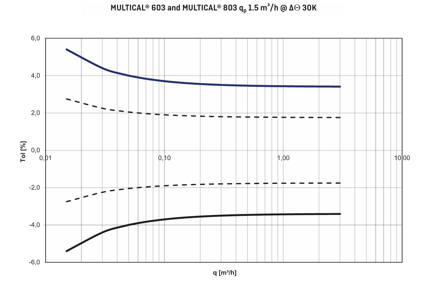
| Calculator | Ec = ± (0,5 + ∆Θ min/∆Θ) % | Ec = ± (0,15 + 2/∆Θ) % |
| ULTRAFLOW® | Ef = ± (2 + 0,02 qp/q), but not over ± 5 % | Ef = ± (1 + 0,01 qp/q) % |
| Sensor set | Et = ± (0,5 + 3 ∆Θ min/∆Θ) % | Et = ± (0,4 + 4/∆Θ) % |
Total typical accuracy of MULTICAL® 603 compared to EN 1434-1 qp 1,5
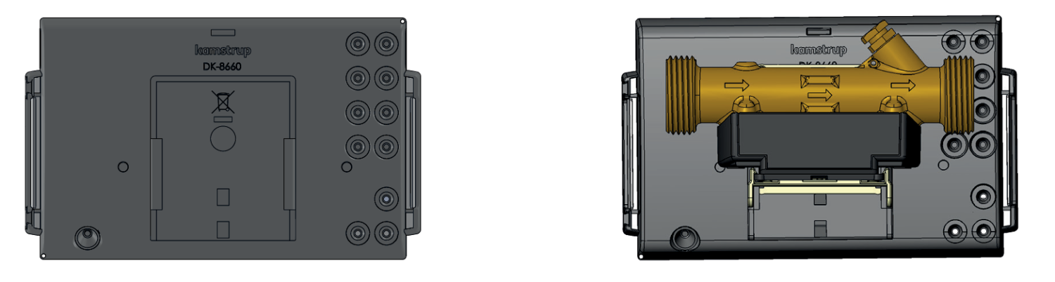
Dimensions MULTICAL® 603
Calculator and wall mount bracket
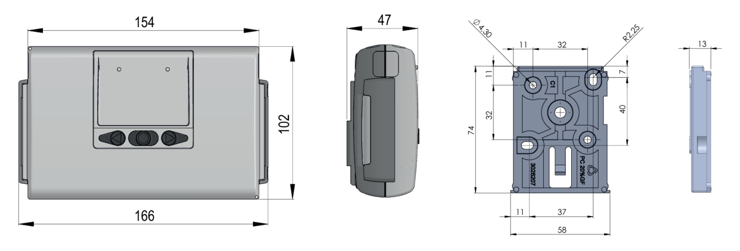
Calculator base separate and mounted on ULTRAFLOW®
MULTICAL® 603 mounted on ULTRAFLOW® with G¾ threaded connection
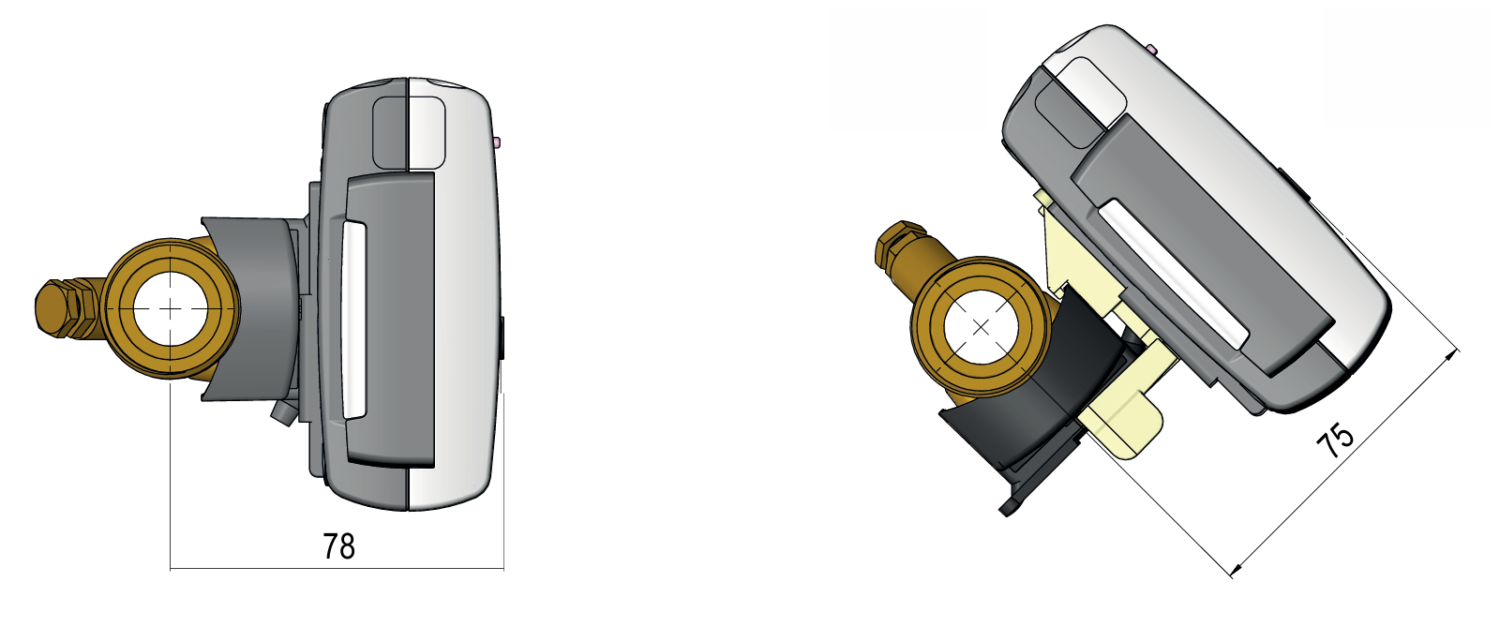
All dimensions in [mm]
Electrical data
| MULTICAL® 603 | |
|---|---|
| Display | LCD – 7 or 8 digits with a digit height of 8,2 mm |
| Resolutions | 9999,999 – 99999,99 – 999999,9 – 9999999 99999,999 – 999999,99 – 9999999,9 – 99999999 |
| Energy units | MWh – kWh – GJ (Standard kWh up to qp 15, MWh from qp 25) |
| Data logger contents | Programmable - all registers can be selected |
| Data logging interval | Programmable - from 1 minute to 1 year |
| Data Logging depth | Programmable - standard: 20 years, 36 months, 460 days, 72 hours |
| Info logger (EEPROM) | 50 info codes (50 latest are shown in the display) |
| Clock/calendar (with backup battery) | Clock, calendar, leap year compensation, target date |
| Daylight saving time/wintertime (DST) | Programmable The function can be disabled so that “technical normal time” is used |
| Clock accuracy | Without external adjustments: Less than 15 minutes/year With external adjustment every 48 hours: Less than 7 s from legal time |
| Power in temperature sensors | <10 µW RMS |
| Supply voltage | 3,6 V DC ± 0,1 V DC |
| Battery type | 3,65 V DC 1 x D-cell |
| Battery life | Up to 16 years at tBAT <30 °C (wall mounting) Up to 14 years at tBAT <40 °C (mounting on the flow sensor) Battery life depends on the communication and configuration parameters of the measuring device, as well as on the transmission interval, the transmission power and the content of the datagrams. |
| Lithium contents | 2 x app. 0,9 g |
| Backup battery (for real-time clock) | 3,0 V DC, BR-Zellen Lithium |
| Network supply | 230 V AC +15/-30 %, 50/60 Hz 24 V AC ±50 %, 50/60 Hz 24 V DC +75/-25 % (24 V DC only High-Power-SMPS) |
| Insulation voltage | 3,75 kV |
| Electricity consumption | <1 W |
| Backup supply | An integrated supercapacitor bridges interruptions caused by short-term network outages (only power supply modules type). |
| Max. cable lengths (max. 6 mm diameter cable) | 2 x 0,25 mm2: 10 m (2-wire) 4 x 0,25 mm2: 100 m (4-wire) |
| Flow measurement | ULTRAFLOW® | Reed contacts | FET contacts | 24 V active pulses |
|---|---|---|---|---|
| CCC code | 1xx-2xx-4xx-5xx-8xx | 0xx | 9xx | 2xx og 9xx |
| EN 1434 pulse class | IC | IB | IB | (IA) |
| Pulse input | 680 kΩ pull-up to 3,6 V | 680 kΩ pull-up to 3,6 V | 680 kΩ pull-up to 3,6 V | 12 mA at 24 V |
| Pulse ON | <0,4 V in > 1 ms | <0,4 V in > 300 ms | <0,4 V in > 30 ms | <4 V in > 3 ms |
| Pulse OFF | > 2,5 V in > 4 ms | > 2,5 V in > 100 ms | > 2,5 V in > 70 ms | > 12 V in > 4 ms |
| Pulse frequency | <128 Hz | <1 Hz | <8 Hz | <128 Hz |
| Integration frequency | <1 Hz | <1 Hz | <1 Hz | <1 Hz |
| Electrical isolation | No | No | No | 2 kV |
| Max. cable length | 10 m | 10 m | 10 m | 100 m |
| Max. cable length with cable extender box | 30 m | 30 m | 30 m | - |
| Pulse inputs In-A/In-B | Electronic contact | Reed contact |
|---|---|---|
| Pulse input | 680 kΩ pull-up to 3,6 V | 680 kΩ pull-up to 3,6 V |
| Pulse ON | <0,4 V in > 30 ms | <0,4 V in > 500 ms |
| Pulse OFF | > 2,5 V in > 30 ms | > 2,5 V in > 500 ms |
| Pulse frequency | <3 Hz | <1 Hz |
| Electrical isolation | No | |
| Max. cable length | 25 m | |
| Requirements for external contact | Leakage current when open <1 µA | |
| Pulse outputs Out-C/Out-D | Opto FET |
|---|---|
| External voltage | 1…48 V DC / V AC |
| Current | <50 mA |
| Residual voltage | Ron ≤ 40 Ω |
| Electrical isolation | 2 kV |
| Max. cable length | 25 m |