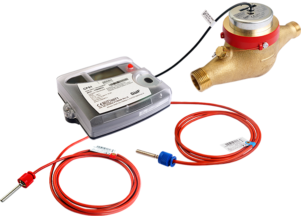
Combined heat and cooling meter for small measuring points
CF-51 and CF-55
Product categories
Heat / Cooling
Combined heat and cooling meter for small
measuring points
Heat / Cooling
Mechanical
Ultrasonic
Smart Building
Your benefits
- Big display:
Easy to read - Universal applicable:
- Wall-mounted model (Volume measuring meter UNICO® and MTW)
- Different power supply possibilities - Option cards for diverse functionalities:
- Economical basic device
- Additional functionalities feasible
Applications
- Metering of heat and/or cooling consumption in building management
- Energy measurement for local or remote reading
Options
- Special version for combined heat/cold measurements (special programming)
- Option cards for:
- M-Bus / water meter inputs
- M-Bus / 2 pulse outputs energy + volume
- M-Bus Power / 2 water meter inputs
- Double M-Bus (only CF-55)
- LonWorks, FTT-10A / 2 water meter inputs (separate supply 24 V AC/DC necessary)
- Modbus RTU (RS485) / 2 water meters inputs (Power supply module 230 V AC necessary) - Optional external EquaScan - wireless pulse Module pMIU
 Documentation: CF-51 Calculator - EPe20526
Documentation: CF-55 Calculator - EPe20527
Downloads
Properties
- Electronic calculator and LCD-resolution 7 digits
- Temperature measuring range 0 - 130 °C
- Temperature sensor Pt 100
- CF-51: 2-wires
- CF-55: 2- or 4-wires - Non-volatile memory EEPROM and 24 month register
- Supply via 12-year battery, mains or M-Bus (pay attention to versions)
- Maximum values with time stamp
- Can be combined with the following volume measuring meters:
- Mechanical impeller meters with Reed-pulser
- Ultrasonic meters with Reed-pulser - Standard EN 1434
 Conformity according European Measuring Instruments Directive (MID)
Product information
Technical Data UNICO®
| Execution | UNICO® | ||||
|---|---|---|---|---|---|
| Nominal diameter | DN | mm | 15 | 20 | 20 |
| Operating pressure | PN | bar | 16 | 16 | 16 |
| Operating pressure (flanged) | PN | bar | - | - | - |
| Connection thread on meter | G…B | Zoll | ¾ | 1 | 1 |
| Connection thread on coupling | R… | Zoll | ½ | ¾ | ¾ |
| Nominal flow rate | qp | m3/h | 1,5 | 1,5 | 2,5 |
| Maximum flow rate | qs | m3/h | 3 | 3 | 5 |
| Minimum flow rate horizontal ±5% | qi | l/h | 30 | 30 | 50 |
| Pulse value of volume measuring meter | l/Imp. | 2,5 | 2,5 | 2,5 | |
| Kvs-value | m3/h | 3 | 3 | 5 | |
| Temperature | °C | 2... 90/120 | 2... 90/120 | 2... 90/120 | |
| Installation position (Flow direction) | ←→↑↓ | ←→↑↓ | ←→↑↓ | ||
| Standard measuring range | qi/qp | 1:50 | 1:50 | 1:50 | |
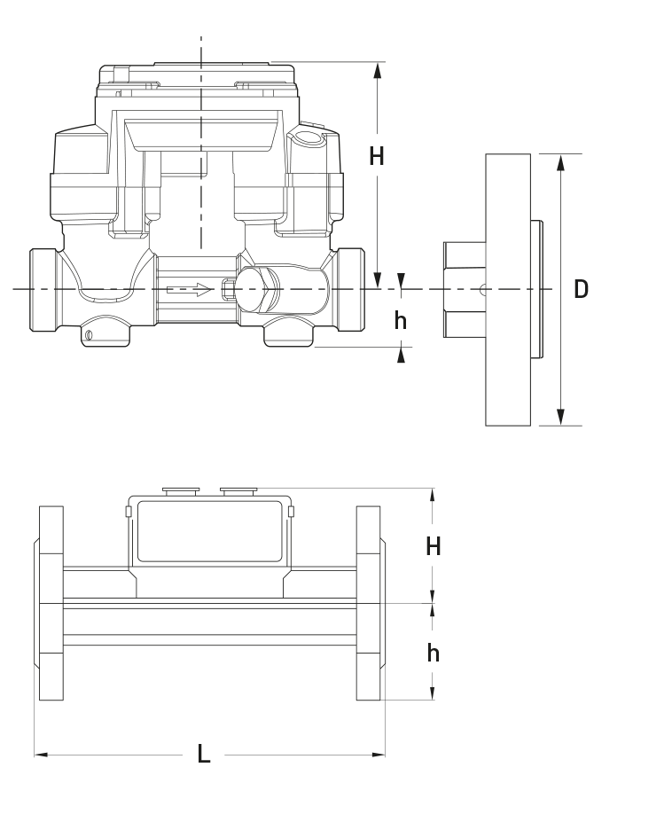
| Dimensions | UNICO® | ||||
|---|---|---|---|---|---|
| Length without couplings | A | mm | 110 | 130 | 130 |
| Length with couplings | mm | 184 | 222 | 222 | |
| Width | B | mm | 72 | 72 | 72 |
| Height with pulser and magnetic protection cover | C | mm | 108 | 108 | 108 |
| Height from pipe centre line | D | mm | 90 | 90 | 90 |
Dimension Diagram CF-51 / CF-55/ UNICO®

Technical Data MTW / MTW-VS / MTW-VF
| Execution | MTW (horizontal) | MTW-VS oder -VF (vertical) 1) | |||||||||
|---|---|---|---|---|---|---|---|---|---|---|---|
| Nominal diameter | DN | mm | 20 | 25 | 32 | 40 | 50 | 20 | 25 | 32 | 40 |
| Operating pressure | PN | bar | 16 | 16 | 16 | 16 | 16 | 16 | 16 | 16 | 16 |
| Operating pressure (flanged) | PN | bar | - | - | - | - | - | - | - | - | - |
| Connection thread on meter | G...B | Zoll | 1 | 1¼ | 1½ | 2 | 2⅜ | 1 | 1¼ | 1½ | 2 |
| Connection thread on coupling | R... | Zoll | 3⁄4 | 1 | 1¼ | 1½ | 2 | 3⁄4 | 1 | 1¼ | 1½ |
| Nominal flow rate | qp | m3/h | 2,5 | 3,5 | 6 | 10 | 15 | 2,5 | 3,5 | 6 | 10 |
| Maximum flow rate | qs | m3/h | 5 | 7 | 12 | 20 | 30 | 5 | 7 | 12 | 20 |
| Minimum flow rate ±5% | qi | l/h | 50 | 70 | 120 | 200 | 300 | 50 | 70 | 120 | 200 |
| Pulse value of volume measuring meter | l/Imp. | 2,5 | 2,5 | 2,5 | 25 | 25 | 2,5 | 2,5 | 2,5 | 25 | |
| Kvs-value | m3/h | 5 | 10 | 12 | 20 | 30 | 5 | 10 | 12 | 20 | |
| Temperature | C° | 2... 90/120 | 2... 90/120 | 2... 90/120 | 2... 90/120 | 2... 90/120 | 2... 90/120 | 2... 90/120 | 2... 90/120 | 2... 90/120 | |
| Installation position | ⇄ | ⇄ | ⇄ | ⇄ | ⇄ | ⇅ | ⇅ | ⇅ | ⇅ | ||
| Standard measuring range | qi/qp | 1:50 | 1:50 | 1:50 | 1:50 | 1:50 | 1:50 | 1:50 | 1:50 | 1:50 | 1:50 |
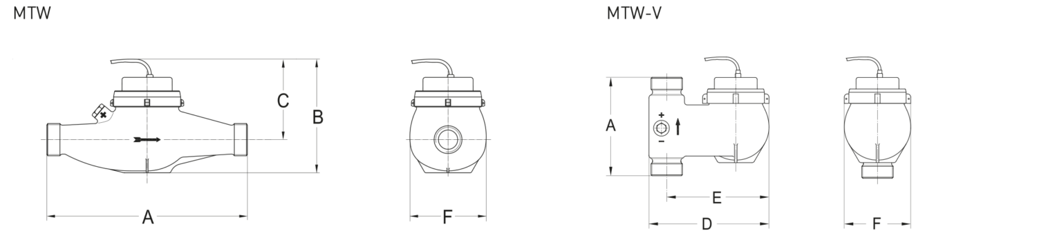
| Dimensions | MTW (horizontal) | MTW-VS oder -VF (vertical) 1) | |||||||||
|---|---|---|---|---|---|---|---|---|---|---|---|
| Length without couplings | A | mm | 2202) | 260 | 260 | 300 | 300 | 105 | 150 | 150 | 200 |
| Length with couplings | mm | 312 | 352 | 372 | 432 | 452 | 197 | 242 | 262 | 332 | |
| Total height | B | mm | 127 | 137 | 137 | 163 | 177 | - | - | - | - |
| Meter height from pipe centre line | C | mm | 87 | 94 | 94 | 117 | 120 | - | - | - | - |
| Meter depth | D | mm | - | - | - | - | - | 148 | 169 | 183 | 226 |
| Meter depth from pipe centre line | E | mm | - | - | - | - | - | 130 | 143 | 156 | 190 |
| Meter width | F | mm | 95 | 100 | 100 | 135 | 151 | 95 | 98 | 101 | 139 |
Dimension Diagram MTW / MTW-V
Technical Data US Echo II

Dimension Diagram US Echo II
Calculator executions
Wall-mounted model (split version)
CF-51
■ ... WBT Battery (12 years)
■ ... WNZ Mains supply (230 V AC)
■ ... WFS Supply via M-Bus
CF-55
■ ... WBT Battery (12 years)
■ ... WNZ Mains supply (230 V AC)
■ ... WFS Supply via M-Bus