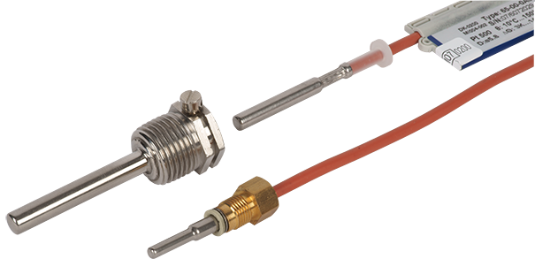
Temperature sensor Pt 500
TDF500 / TF500
Product categories
2-wire temperature sensor for heat and cooling meters
Heat / Cooling
Smart City
Smart Building
Your benefits
- High accuracy:
Low measurement errors - Short response time:
Accurate instantaneous values - Various versions:
Flexible insert - CH refrigeration approval (METAS) incl. initial calibration:
Approved for use in clearing traffic
Applications
- Temperature detection for heating and cooling measurements in the building services sector
- Temperature detection for energy measurements in billing transactions for district heating supplies
Downloads
Properties
- Direct installation sensor or sensor for thermowell installation
- Temperature sensor Pt 500
- Cable sensor with silicone cable, 2-wire technology
- Supplied in pairs
- Standard EN 1434
- Temperature measuring range 2 to 150°C
- Type examination/approval:
- Heat: Conformity to European Measuring Instruments Directive (MID)
- Cold: CH approval (METAS) incl. initial calibration
Product information
TDF Anwendung

Approval and verification
| MID approval DK-0200-MI004-046 | |
|---|---|
| Temperature range | θ: 2….150 °C |
| Temperature difference | ΔΘ: 3….140 K |
| CH approval (METAS) incl. initial calibration CH-T2-21627 -00 | |
|---|---|
| Temperature range | θ: 2….150 °C |
| Temperature difference | ΔΘ: 3….140 K |
Pairing and calibration according to EN1434-5:2015.
Technical data
| Series |  Direct installation sensor TDF500 Direct installation sensor TDF500 |
Direct installation sensor TDF500 |
 Immersion sleeve sensor TF500, Ø5.8 Immersion sleeve sensor TF500, Ø5.8 |
|---|---|---|---|
| Sensor length | 27.5mm | 38mm | 46mm |
| Measuring resistor | Pt 500 | ||
| Resistance to | EN 60751 | ||
| Connection thread | M10x1 | M10x1 | - |
| Time constant T0.5 | 2s | 2s | 4s |
| Minimum immersion depth | 15mm | 15mm | 18mm |
| Material | AISI 316L W-Nr. 1.4404 | ||
| Silicone cable | 2x0.22mm2 | ||
| Cable length | 1.5m, 3m | 1.5m, 3m | 1.5m, 3m, 5m, 10m |
| Temperature measuring range | 2 bis 150°C | ||
| Temperature difference | 3 bis 140K | ||
| Ambient temperature | -10 bis +70°C | ||
| Storage temperature | -25 bis +70°C | ||
| Medium | District heating water | ||
| Medium temperature | 0...150 °C, short-term 160 °C | ||
| Air humidity | <98 % rH condensing | ||
| Tightness | IP68 | ||
| Approved mechanical classes | M1, M2 | ||
| Approved pressure levels | PN16, PN25, PS25 | ||
Dimensions
Direct installation sensor TDF500, 27.5mm

Immersion sleeve sensor TF500, Ø5.8

Immersion sleeves and nipples
Immersion sleeves for ø5.8 mm temperature sensors

| Technical data | |
|---|---|
| Installation lengths | 65 mm, 90 mm, 140 mm |
| Thread | Conical thread R½ |
| Material | AISI 304/W.-Nr 1.4301 |
| Time constant T0.5 | Max. 8 s |
| Pressure level | PN16/PN25, PS25 |
| Highest flow rate | 3 m/s |
| Highest service temperature | 150 °C |
| Approved mechanical classes | M1, M2 |
EN 1434 Tauchhülsen für ø5,8 mm Temperaturfühler

| Technische Daten | |
|---|---|
| Installation lengths L | 65 mm, 85 mm, 120 mm, 210 mm |
| Thread | Straight thread G½B |
| Gasket | Copper seal (supplied in bag with 2 immersion sleeves) |
| Material | AISI 316L/W.-Nr. 1.4404 |
| Time constant T0.5 | Max. 14 s with ø5.8 mm temperature sensor |
| Pressure level | PN16/PN25, PS25 |
| Highest flow rate | 3 m/s |
| Highest service temperature | 150 °C |
| Approved mechanical classes | M1, M2 |
Nipple

Connection R½ or R¾
Material MS 58 Bb
Nipples may be used in both PN16 and PN25 installations.
Assembly examples

Example 1
Direct installation sensor, mounted in a T-piece with transition nipple

Example 2
Immersion sleeve sensor, mounted in a T-piece with immersion sleeve
■ Observe the flow direction
Sealing examples

Installation note
Installing the sensors
The supply and return sensor cables must always be the same length and have the same cross-section in order to avoid different cable resistances. The supplied cable of the flow and return sensor must not be shortened or lengthened in accordance with EN 1434-2 chapter 3.3.4. The sensors are paired. They are supplied in pairs and must also be used in pairs for the same calculator. The active sensor part should be located in the middle of the pipe; the tip should be directed towards the flow if possible.
Installation recommendations
Ensure symmetrical positioning of the flow and return sensors, i.e. the two sensors in a measuring system should be installed in the same way (e.g. both in pipe bends). Direct installation sensors must not be mixed with immersion sleeve sensors. This ensures that the temperature difference is measured with the best possible accuracy.
Installing the immersion sleeves
When installing the thermowells, ensure that the heating water flows around them over their entire length.
Important: Take any pipe insulation into account when dimensioning. Provide sufficient free space so that the sensor can be removed from the permanently installed immersion sleeve.
In order to achieve the best possible measuring accuracy, it is necessary to install the manufacturer's original immersion sleeves in conjunction with the temperature sensors supplied.
Insulation
Any cable insulation must be designed in such a way that the locking screw of the sensor immersion sleeve remains accessible at all times and the sensor can be easily removed for service and maintenance.