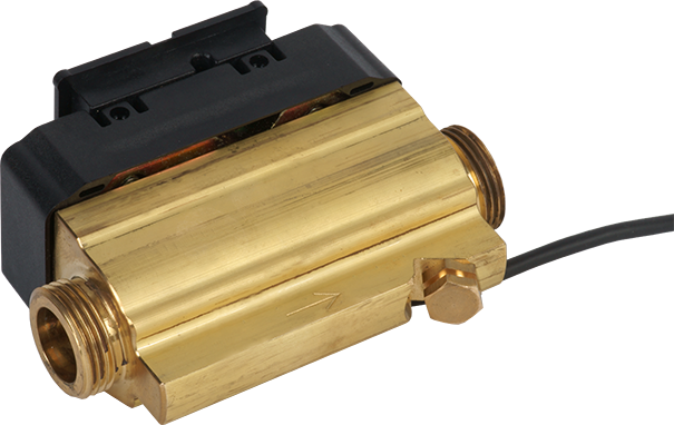
Ultrasonic volume measuring device
ULTRAFLOW® 54
Product categories
Durable, wear-free ultrasonic volume measuring device. Especially suitable for district heating/cooling applications (main meters, transfer stations, etc.) in billing transactions.
Heat / Cooling
Ultrasonic
Smart City
Smart Building
Your benefits
- Durable, wear-free ultrasonic volume measuring device:
High measurement stability and operational reliability - Compact design:
Requires little installation space on site - High resolution of pulse values:
Precise instantaneous values - CH refrigeration certification (METAS) incl. initial calibration:
Approved for use in commercial transactions
Applications
- Particularly suitable for district heating/cooling applications (main meters, transfer stations, etc.) in billing transactions
- Replacement of mechanical impeller heat meters
- Heat and/or cooling consumption measurement in building services engineering
- Can only be used with MULTICAL® series calculators
Options
- Pulse transmitter with its own power supply for cable lengths >10 m
Properties
- Nominal diameters:
Heating: DN 20 to DN 300
Combined heating/cooling: DN 150 to DN 300
Cooling: DN 150 to DN 300 - Nominal flow rates:
Heat: qp 1,5 to qp 1000
Heat/cooling combined: qp 150 to qp 1000
Cooling: qp 150 to qp 1000 - Low pressure loss
- No moving parts
- Signal transmission to the computing unit and power supply to the volume measuring device via a 3-wire cable
- Medium temperature:
Heat: 15 to 130 °C
Heat/cooling combined: 2 to 130 °C
Cooling: 2 to 130 °C
From 90 °C, a flange meter, wall mounting of the electronic unit of the volume measuring part from DN 150, and relocation of the calculator are recommended. - Type approval/certification:
- Heat: Conformity acc. European Measuring Instruments Directive (MID)
- Cold: Swiss certification (METAS) including initial calibration
Product information
Technical Data ULTRAFLOW® 54 (DN 20 - 65)
| Series | ULTRAFLOW® 54 | ||||||||||||
|---|---|---|---|---|---|---|---|---|---|---|---|---|---|
| Nominal diameter | DN | mm | 20 | 20 | 25 | 25 | 25 | 25 | 32 | 40 | 40 | 50 | 65 |
| Nominal flow rate | qp | m3/h | 1,5 | 2,5 | 3,5 | 3,5 | 6 | 6 | 6 | 10 | 10 | 15 | 25 |
| Nominal pressure | PN | bar | - | - | 16 | - | 16 | - | - | 16 | - | - | - |
| Nominal pressure with flanges | PN | bar | 25 | 25 | - | 25 | - | 25 | 25 | - | 25 | 25 | 25 |
| Connection thread on meter | G…B | Inch | - | - | 1¼ | - | 1¼ | - | - | 2 | - | - | - |
| Maximum flow rate | qs | m3/h | 3 | 5 | 7 | 7 | 12 | 12 | 12 | 20 | 20 | 30 | 50 |
| Minimum flow rate +/- 5 % | qi | l/h | 15 | 25 | 35 | 35 | 60 | 60 | 60 | 100 | 100 | 150 | 250 |
| Kvs value | m3/h | 3,2 | 13,4 | 13,4 | 13,4 | 13,4 | 13,4 | 13,4 | 40 | 40 | 40 | 102 | |
| Starting flow | l/h | 3 | 5 | 7 | 7 | 12 | 12 | 12 | 20 | 20 | 30 | 50 | |
| Temperature | max. °C | 130 | 130 | 130 | 130 | 130 | 130 | 130 | 130 | 130 | 130 | 130 | |
| Standard measuring range | qi / qp | 1:100 | 1:100 | 1:100 | 1:100 | 1:100 | 1:100 | 1:100 | 1:100 | 1:100 | 1:100 | 1:100 | |
| Dimensions and weights | |||||||||||||
|---|---|---|---|---|---|---|---|---|---|---|---|---|---|
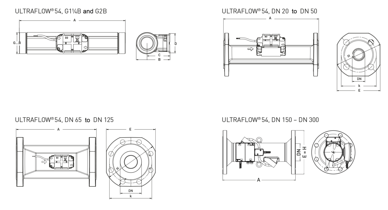
| Length without couplings | A | mm | - | - | 260 | - | 260 | - | - | 300 | - | - | - |
| Total height | B | mm | - | - | 80 | - | 80 | - | - | 96 | - | - | - |
| Height from pipe center line | C | mm | - | - | 58 | - | 58 | - | - | 65 | - | - | - |
| Width | D | mm | - | - | 55 | - | 55 | - | - | 55 | - | - | - |
| Length with flanges | A | mm | 190 | 190 | - | 260 | - | 260 | 260 | - | 300 | 270 | 300 |
| Height with flanges | E | mm | 95 | 95 | - | 106 | - | 106 | 128 | - | 136 | 145 | 168 |
| Flange outer diameter1) | H | mm | 105 | 105 | - | 115 | - | 115 | 140 | - | 150 | 165 | 185 |
| Bolt circle diameter1) | K | mm | 75 | 75 | - | 85 | - | 85 | 100 | - | 110 | 125 | 145 |
| Number of screws1) | Pcs. | 4 | 4 | - | 4 | - | 4 | 4 | - | 4 | 4 | 8 | |
| Weight without couplings | app. kg | - | - | 2,3 | - | 2,3 | - | - | 4,5 | - | - | - | |
| Weight with flanges | app. kg | 2,9 | 2,9 | - | 5,0 | - | 5,0 | 5,2 | - | 8,3 | 10,1 | 13,2 | |
1) DIN EN 1092
Technical Data ULTRAFLOW® 54 (DN 80 - 300)
| Series | ULTRAFLOW® 54 | ||||||||||||||
|---|---|---|---|---|---|---|---|---|---|---|---|---|---|---|---|
| Nominal diameter | DN | mm | 80 | 100 | 100 | 125 | 150 | 150 | 150 | 200 | 200 | 250 | 250 | 250 | 300 |
| Nominal flow rate | qp | m3/h | 40 | 60 | 100 | 100 | 150 | 250 | 400 | 400 | 600 | 400 | 600 | 1000 | 1000 |
| Nominal pressure | PN | bar | - | - | - | - | - | - | - | - | - | - | - | - | - |
| Nominal pressure with flanges | PN | bar | 25 | 25 | 25 | 25 | 25 | 25 | 25 | 25 | 25 | 25 | 25 | 25 | 16 |
| Connection thread on meter | G…B | Inch | - | - | - | - | - | - | - | - | - | - | - | - | - |
| Maximum flow rate | qs | m3/h | 80 | 120 | 200 | 200 | 300 | 500 | 800 | 800 | 1200 | 800 | 1200 | 2000 | 2000 |
| Minimum flow rate +/- 5% | qi | l/h | 400 | 600 | 1000 | 1000 | 1500 | 2500 | 4000 | 4000 | 6000 | 4000 | 6000 | 10000 | 10000 |
| Kvs value | m3/h | 179 | 373 | 373 | 373 | 1060 | 1060 | 2000 | 4040 | 4040 | 4040 | 4040 | 8160 | 8160 | |
| Starting flow | l/h | 80 | 120 | 200 | 200 | 300 | 500 | 800 | 800 | 1200 | 800 | 1200 | 2000 | 2000 | |
| Temperature | max. °C | 130 | 130 | 130 | 130 | 130 | 130 | 130 | 130 | 130 | 130 | 130 | 130 | 130 | |
| Standard measuring range | qi / qp | 1:100 | 1:100 | 1:100 | 1:100 | 1:100 | 1:100 | 1:100 | 1:100 | 1:100 | 1:100 | 1:100 | 1:100 | 1:100 | |
| Dimensions and weights | |||||||||||||||
|---|---|---|---|---|---|---|---|---|---|---|---|---|---|---|---|
| Length without couplings | A | mm | - | - | - | - | - | - | - | - | - | - | - | - | - |
| Total height | B | mm | - | - | - | - | - | - | - | - | - | - | - | - | - |
| Height from pipe center line | C | mm | - | - | - | - | - | - | - | - | - | - | - | - | - |
| Width | D | mm | - | - | - | - | - | - | - | - | - | - | - | - | - |
| Length with flanges | A | mm | 300 | 360 | 360 | 350 | 500 | 500 | 500 | 500 | 500 | 600 | 600 | 600 | 500 |
| Height with flanges | E | mm | 184 | 220 | 220 | 260 | 300 | 300 | 300 | 360 | 360 | 425 | 425 | 425 | 460 |
| Flange outer diameter1) | H | mm | 200 | 235 | 235 | 270 | 300 | 300 | 300 | 360 | 360 | 425 | 425 | 425 | 460 |
| Bolt circle diameter1) | k | mm | 160 | 190 | 190 | 220 | 250 | 250 | 250 | 310 | 310 | 370 | 370 | 370 | 410 |
| Number of screws1) | Pcs. | 8 | 8 | 8 | 8 | 8 | 8 | 8 | 12 | 12 | 12 | 12 | 12 | 12 | |
| Weight without couplings | app. kg | - | - | - | - | - | - | - | - | - | - | - | - | - | |
| Weight with flanges | app. kg | 16,8 | 21,7 | 21,7 | 28,2 | 37 | 37 | 36 | 49 | 49 | 79 | 79 | 75 | 76 | |
1) DIN EN 1092
Dimension Diagram
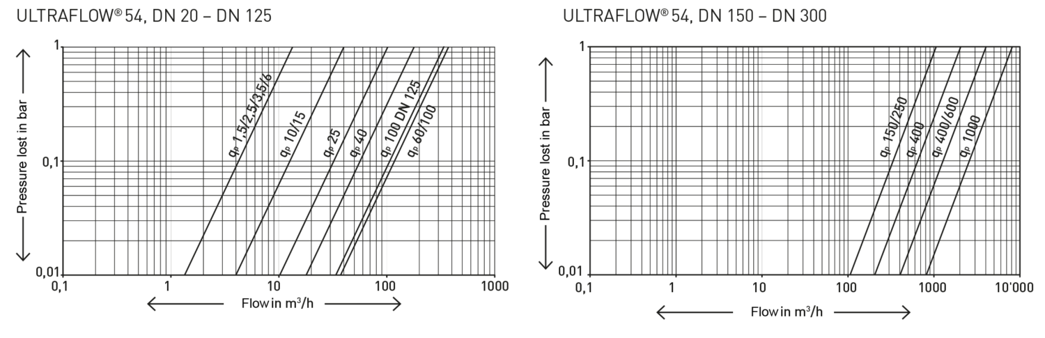
Typical Head Loss Curve
Installation positions
| Pipe: | horizontal | |
| vertical | ||
| inclined | ||
| Head of the meter | to the side | |
| ULTRAFLOW® 54 DN 20 – DN 125: | ± 45° | |
| ULTRAFLOW® 54 DN 150 – DN 300: | ± 90° |
Electrical connections
| ULTRAFLOW® 54 | → | MULTICAL® |
| Blue (Masse) / 11 A | → | 11 |
| Red (Supply) / 9 A | → | 9 |
| Yellow (Signal) / 10 A | → | 10 |
Installation note
For ULTRAFLOW® 54 ≤ DN 125 (100 m3/h), the black electronics housing must be installed on the side (for horizontal installation). ULTRAFLOW® 54 can be rotated up to ± 45° in relation to the pipe axis. ULTRAFLOW® 54 does not require a straight inlet or outlet section. ULTRAFLOW® 54 must not be exposed to pressure lower than the ambient pressure (vacuum).
For ULTRAFLOW® 54 ≥ DN 150 (150 m3/h), it is recommended that the black electronics housing be installed on the side (for horizontal installation) in order to better measure any layer flows. However, ULTRAFLOW® 54 may also be rotated up to ± 90° in relation to the pipe axis. ULTRAFLOW® 54 does not require a straight inlet or outlet section. ULTRAFLOW® 54 must not be exposed to pressure lower than the ambient pressure (vacuum).
Installation recommendations
Strong flow disturbances mostly occur in connection with valves and pumps that aren't fully open, as well as multiple bends. The minimal distances listed below have proven effective when installing thermal energy meters (best-practice approach):
| Minimum recommended distances | Ultrasonic volume measuring device DN 20 - 80 | Ultrasonic volume measuring device DN 100 - 300 |
|---|---|---|
| If valves are not fully open | 20 x DN | 40 x DN |
| On the pressure side of pumps | 20 x DN | 20 x DN |
| For multiple arches | 5 x DN | 5 x DN |
Materials
Parts in contact with medium
ULTRAFLOW® 54 qp 1,5 and qp 2,5
Housing with flange connection: Stainless steel, W. No. 1.4308
Sensor: Stainless steel, W. No. 1.4401
Seals: EPDM
Reflector: Thermoplastic, PESU 30 % GF and stainless steel, comparable to AISI 304 or AISI 316
Measuring tube: Thermoplastic, PESU 30 % GF
ULTRAFLOW® 54 qp 3,5 to qp 100
Housing with threaded connection: Dezincification-resistant brass
Housing with flange connection: Stainless steel, W. No. 1.4308
Sensor: Stainless steel, W. No. 1.4401
Seals: EPDM
Reflector: Thermoplastic, PESU 30 % GF and stainless steel, comparable to AISI 304 or AISI 316
Measuring tube: Thermoplastic, PESU 30 % GF
ULTRAFLOW® 54 qp 150 to qp 1000
Housing with flange connection: Stainless steel, W. No. 1.4301
Electronic housing
Base: Thermoplastic, PC 10 % GF
Cover: Thermoplastic, PC 20 % GF
Connection cable
Cable: Silicone (3 x 0,5 mm2)