
Thermal energy meter
MULTICAL® 403
Kategorie produktowe
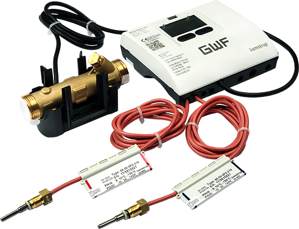
MULTICAL® 403 is a static heat meter, cold meter, or combined heat/cold meter based on the ultrasonic principle. The meter is designed for energy measurement in almost all system configurations using water as the energy carrier. MULTICAL® 403 consists of a calculator, a flow sensor, and two temperature sensors. MULTICAL® 403 was developed for measuring energy consumption in apartments, single-family and multi-family homes, housing associations, apartment buildings, and small industrial facilities.
Ciepłomierze / Chłodomierze
Ultradźwiękowe
Z przewodem
Impulse,
M-Bus,
Modbus,
BacNET
Bezprzewodowe
wM-Bus,
LoRaWAN
Smart City
Smart Building
Korzyści
- Ultrasonic technology:
Long term stable energy measurement with highest accuracy - Modular design with high flexibility:
Base device expandable, reduced inventory - Comprehensive data logger:
Access to information for analysis and optimization - One time reprogramming of metrological parameters on site without breaking the MID seal:
Flexibility and time saving during commissioning - Option cards for various functions:
- Cost effective base device
- Functions can be added later - Swiss cooling approval (METAS) incl. initial verification:
Approved for billing purposes
Zastosowanie
- Especially suitable for district heating billing applications (main meters, transfer stations, etc.)
- Replacement of mechanical turbine heat meters
- Heating and/or cooling consumption measurement in building services
Opcje
- Option cards for:
- M-Bus with 2 water meter inputs
- M-Bus with 2 pulse outputs energy and volume
- Wireless OMS T1 868 MHz (battery lifetime 11 years)
- 2 active analog outputs 0/4 to 20 mA (mains power supply required)
- BACnet MS/TP RS485 with 2 water meter inputs (mains power supply required)
- Modbus RTU RS485 with 2 water meter inputs (mains power supply required)
- BACnet IP with 2 water meter inputs (high-power power supply required)
- LoRaWAN internal or external antenna
Pliki do pobrania
Cechy
- Nominal diameters DN 15 to DN 50
- Nominal flow rates qp 0,6 to qp 15
- Any installation position
- Low pressure loss
- Medium temperature 2 to 90 °C (up to 130 °C wall mounting)
- Calculator temperature range 2 to 180 °C
- Mains supply 230 V AC, 24 V AC supply or with 16-year battery (wall mounting) respectively 14 years (compact mounting)
- Integrated real time clock and data logger
- Large LCD display 7 or 8 digits
- Temperature sensors Pt 500
- Storage of last 36 monthly and 20 yearly values
- Type approval / Certification:
- Heating: Conformity according to the European Measuring Instruments Directive (MID)
- Cooling: Swiss approval (METAS) including initial verification
Product information
Technical Data
| Series | |||||||||||||
|---|---|---|---|---|---|---|---|---|---|---|---|---|---|
| Nominal flow rate | qp | m3/h | 0,6 | 0,6 | 1,5 | 1,5 | 2,5 | 3,5 | 6 | 6 | 10 | 10 | 15 |
| Nominal diameter | DN | mm | 15 | 20 | 15 | 20 | 20 | 25 | 25 | 25 | 40 | 40 | 50 |
| Connection thread on meter | G...B | Inch | ¾ | 1 | ¾ | 1 | 1 | 1¼ | 1¼ | Flange | 2 | Flange | Flange |
| Maximum flow rate | qs | m3/h | 1,2 | 1,2 | 3 | 3 | 5 | 7 | 12 | 12 | 20 | 20 | 30 |
| Minimum flow rate | qi | l/h | 6 | 6 | 15 | 15 | 25 | 35 | 60 | 60 | 100 | 100 | 150 |
| Starting value | l/h | 3 | 3 | 3 | 3 | 5 | 7 | 12 | 12 | 20 | 20 | 25 | |
| Kvs value | m3/h | 3,46 | 3,46 | 4,89 | 4,89 | 8,15 | 13,42 | 24,5 | 24,5 | 40,83 | 40,83 | 40,09 | |
| Maximum pressure | PN | bar | 25 | ||||||||||
| Standard measuring range | qp / qi | 100:1 | |||||||||||
| Protection class | Calculator IP54 Flow sensor IP68 | ||||||||||||
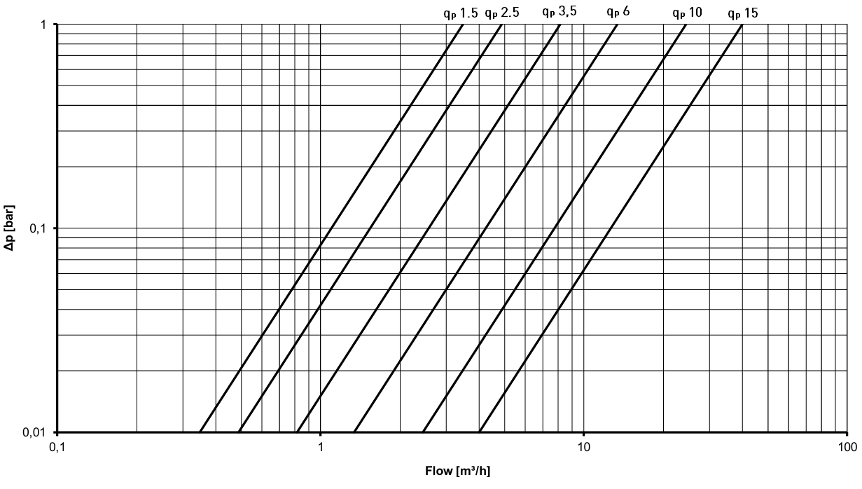
Pressure loss
The pressure loss in a flow sensor is stated as the maximum pressure loss at qp.
According to EN 1434, the maximum pressure loss must not exceed 0,25 bar.
Mechanical design MULTICAL® 403
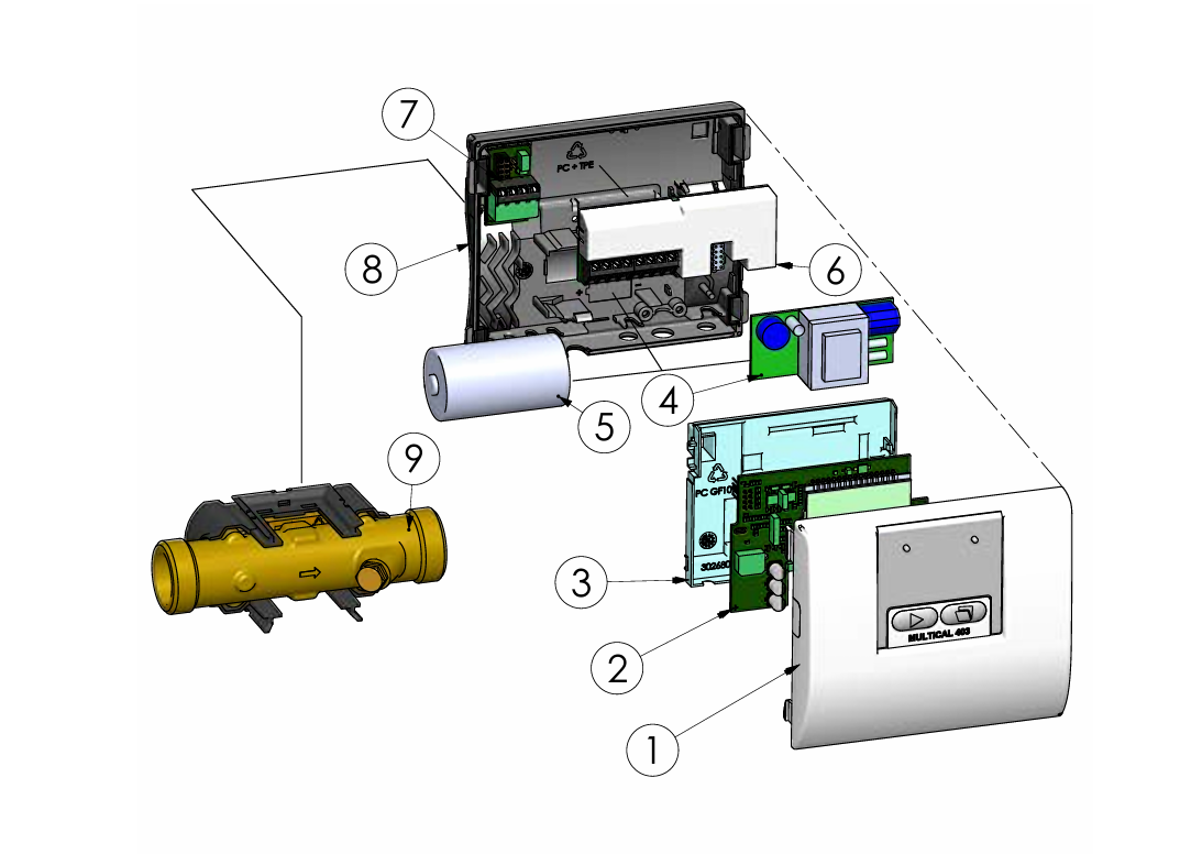
1 Top section with front buttons and laser marking
2 Circuit board with microcontroller, flow ASIC, display, etc.
3 Circuit board cover (may only be opened by an authorized testing laboratory)
4 Either a power supply module can be mounted...
5 ...or a battery can be mounted
6 Data module, e. g., M-Bus
7 Connection for temperature sensors
8 Bottom section
9 Flow sensor (IP68)
Mechanical data
| MULTICAL® 403 | |
|---|---|
| Weight (depending on the flow sensor size) | 0,9 – 8,6 kg |
| Ambient temperature | 5…55 °C, non-condensing, closed location (indoor installation) |
| Media temperatures | 2…130 °C (Heat, Heat-/Cooling) 2...50 °C (Cooling) (At media temperatures below the ambient temperature or above 90 °C, wall-mounting of the calculator is recommended) |
| Medium in flow sensor | Water (district heating water as described in CEN TR 16911 and AGFW FW510) |
| Storage temperature | -25…60 °C (drained flow sensor) |
| Flow sensor cable | 1,5 m (the cable is non-detachable) |
| Temperature sensor cables | 1,5 m, 3 m, 10 m |
| Materials | |
|---|---|
| Case, coupling | Hot forged, dezincification-resistant brass (CW 602N) |
| Case, flange | Stainless steel, W. No. 1.4308 |
| Transducer | Stainless steel, W. No. 1.4404 |
| O-rings | EPDM |
| Measuring tube | Thermoplastic, PES 30 % GF |
| Reflektors | Thermoplastic, PES 30 % GF and stainless steel, W. No. 1.4306 |
| Flow sensor cover | Thermoplastic, PC 20 % GF |
| Wall bracket | Thermoplastic, PC 20 % GF |
| Calculator Top | Thermoplastic, PC 10 % GF with TPE (thermoplastic elastomer) |
| Calculator Base | Thermoplastic, PC/ABS |
| Calculator internal cover | Thermoplast, PC 10 % GF |
| Cables | Silicone cable with inner Teflon insulation |
Approved meter data
| MULTICAL® 403 | |
|---|---|
| Heat meter | DK-0200-MI004-037 |
| Cooling meter | TS 27.02 009 |
| Bifunctional heat/cooling meter | DK-0200-MI004-037 und TS 27.02 009 |
| Temperature range | θ: 2 °C…180 °C |
| Differential range | ∆Θ: 3 K…178 K |
| Total Temperature range | The stated minimum temperatures only relate to the type approval. The meter has no cut-off for low temperature and thus measures down to 0,01 °C and 0,01 K. |
| Standards and norms | EN 1434:2007/AC:2007 EN 1434:2015+A1:2018 EN 1434:2022 BEK1178 |
| EU directives | Measuring Instruments Directive (MID) Low Voltage Directive (LVD) Electromagnetic Compatibility Directive (EMC) Radio Equipment Directive (RED) Restriction of Hazardous Substances Directive (RoHS) Pressurised Equipment Directive (PED) |
| EN 1434 designation | Environmental class A and C |
| MID Mechanical environment | Class M1 and M2 |
| MID Electromagnetic environment | Class E1 |
| Temperature sensor | Pt 500 – EN 60751 |
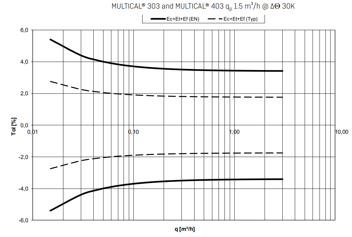
Accuracy
| Meter components | MPE according to EN 1434-1 | MULTICAL® 403, typical accuracy |
|---|---|---|
| Calculator | Ec = ± (0,5 + ∆Θ min/∆Θ) % | Ec = ± (0,15 + 2/∆Θ) % |
| Flow sensor | Ef = ± (2 + 0,02 qp/q), but not over ± 5 % | Ef = ± (1 + 0,01 qp/q) % |
| Sensor set | Et = ± (0,5 + 3 ∆Θ min/∆Θ) % | Et = ± (0,4 + 4/∆Θ) % |
Typical total accuracy of MULTICAL® 403 compared to EN 1434-1 qp 1,5
Dimensioned sketches
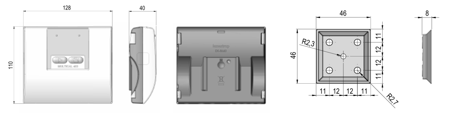
Calculator and wall mount bracket
Flow sensor with G¾ and G1 thread connection
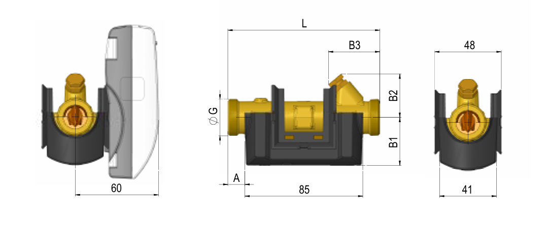
| Flow sensor G¾ and G1 | |||||||
|---|---|---|---|---|---|---|---|
| Nominal flow rate | qp | m3/h | 0,6 + 1,5 | 1,5 | 2,5 | 0,6 + 1,5 | 2,5 |
| Thread | G | Inch | G¾B | G1B | G1B | G1B | G1B |
| Total length | L | mm | 110 | 130 | 130 | 190 | 190 |
| Total height | H | mm | 67 | 70 | 76 | 76 | 76 |
| Total width | W | mm | 48 | 48 | 48 | 48 | 48 |
| Dimension A | A | mm | 12 | 22 | 22 | 22 | 22 |
| Dimension B1 | B1 | mm | 35 | 38 | 38 | 38 | 38 |
| Dimension B2 | B2 | mm | 32 | 32 | 38 | 38 | 38 |
| Dimension B3 | B3 | mm | 38 | 48 | 48 | 78 | 78 |
| Weight | app. kg | 0,9 | 1,0 | 1,0 | 1,1 | 1,2 | |
Flow sensor with G5/4 and G2 threaded connections
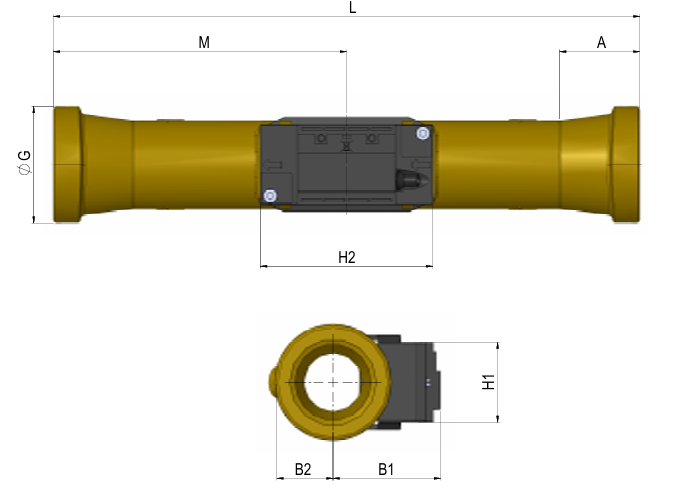
| Flow sensor G5/4 and G2 | |||||
|---|---|---|---|---|---|
| Nominal flow rate | qp | m3/h | 3,5 | 6 | 10 |
| Thread | G | Inch | G5/4B | G5/4B | G2B |
| Total length | L | mm | 260 | 260 | 300 |
| Total height | H | mm | 71 | 73 | 84 |
| Total width | W | mm | 42 | 42 | 60 |
| Dimension M | M | mm | 130 | 130 | 130 |
| Dimension H2 | H2 | mm | 88 | 88 | 88 |
| Dimension A | A | mm | 16 | 16 | 40,2 |
| Dimension B1 | B1 | mm | 51 | 53 | 55 |
| Dimension B2 | B2 | mm | 20 | 20 | 29 |
| Dimension H1 | H1 | mm | 41 | 41 | 41 |
| Weight | app. kg | 2,0 | 2,1 | 3,0 | |
Flow sensor with DN 25, DN 40 and DN 50 flange connection
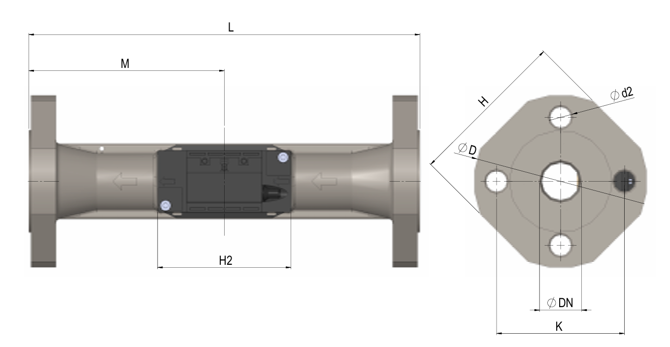
| Flow sensor DN 25, DN 40 and DN 50 flange | |||||
|---|---|---|---|---|---|
| Nominal flow rate | qp | m3/h | 6 | 10 | 15 |
| Nominal diameter | DN | mm | 25 | 40 | 50 |
| Total length | L | mm | 260 | 300 | 270 |
| Total height | H | mm | 106 | 140 | 145 |
| Dimension M | M | mm | 130 | 150 | 155 |
| Dimension H2 | H2 | mm | 88 | 88 | 88 |
| Dimension D | D | mm | 115 | 150 | 165 |
| Dimension K | K | mm | 85 | 110 | 125 |
| Quantity of bolts | Pcs. | 4 | 4 | 4 | |
| Bolt thread | M12 | M12 | M12 | ||
| Bolt diameter | d2 | mm | 14 | 18 | 18 |
| Weight | app. kg | 4,6 | 7,5 | 8,6 | |
Electrical data
| MULTICAL® 403 | |
|---|---|
| Display | LCD – 7 or 8 digits with a digit height of 8,2 mm (Standard 7) |
| Resolutions | 9999,999 – 99999,99 – 999999,9 – 9999999 99999,999 – 999999,99 – 9999999,9 – 99999999 |
| Energy units | MWh – kWh – GJ (Standard kWh) |
| Data logger contents | Programmable - all registers can be selected |
| Data logging interval | Programmable - from 1 minute to 1 year |
| Data Logging depth | Programmable - standard: 20 years, 36 months, 460 days, 72 hours |
| Info logger (EEPROM) | 50 info codes (50 latest are shown in the display) |
| Clock/calendar (with backup battery) | Clock, calendar, leap year compensation, target date |
| Daylight saving time/wintertime (DST) | Programmable The function can be disabled so that “technical normal time” is used |
| Clock accuracy | Without external adjustments: Less than 15 minutes/year With external adjustment every 48 hours: Less than 7 s from legal time |
| Data communication | KMP protocol with CRC16 is used for optical communication and modules |
| Power in temperature sensors | <10 µW RMS |
| Supply voltage | 3,6 V DC ± 0,1 V DC |
| Battery type | 3,65 V DC 1 x D-cell |
| Battery life | Up to 16 years @ tBAT<30 °C The battery lifetime is affected by the meter’s communication and setup parameters as well as transmission interval, transmission power and datagram contents. |
| Lithium contents | 2 x app. 0,9 g |
| Backup battery (for real-time clock) | 3,0 V DC, BR-Zellen Lithium |
| Network supply | 230 V AC +15/-30 %, 50/60 Hz 24 V AC ±50 %, 50/60 Hz 24 V DC +75/-25 % (24 V DC just for High-Power-SMPS) |
| Insulation voltage | 3,75 kV |
| Electricity consumption | <1 W |
| Backup supply | An integrated supercapacitor bridges interruptions caused by short-term network outages (only power supply modules type). |
MULTICAL® 403 Pulse in- and outputs
| Pulse inputs In-A/In-B | Electronical contact | Reed contact |
|---|---|---|
| Pulse input | 680 kΩ pull-up for 3,6 V | 680 kΩ pull-up for 3,6 V |
| Pulse ON | <0,4 V for > 30 ms | <0,4 V for > 500 ms |
| Pulse OFF | > 2,5 V for > 30 ms | > 2,5 V for > 500 ms |
| Pulse frequency | <3 Hz | <1 Hz |
| Electrical isolation | No | |
| Max. cable length | 25 m | |
| Requirements for external contact | Leakage current at function open <1 µA | |
| Pulse outputs Out-C/Out-D | Opto FET |
|---|---|
| External voltage | 1…48 V DC / V AC |
| Current | <50 mA |
| Residual stress | Ron ≤ 40 Ω |
| Electrical isolation | 2 kV |
| Max. cable length | 25 m |
Temperature sensor
| Temperature sensor | |
|---|---|
| Sensor element | Pt 500 |
| Version | ■ Direct immersion sensor ■ Thermowell measurement |
| Connection diagram | 2-wire connection |
| Installation length | 65 mm / 90 mm / 140 mm |
| Cable lengths | 2 x 1,5 m / 2 x 3 m |
Installation note
The MULTICAL® 403 requires neither a straight inlet nor outlet pipe section. The MULTICAL® 403 must not be exposed to pressure below ambient pressure (vacuum).
Installation recommendations
Significant flow disturbances usually occur in connection with partially open valves, pumps and multiple bends. The minimum distances listed below have proven effective for the installation of thermal energy meters (best practice approach):
| Minimum recommended distances | |
|---|---|
| Inlet section | 5 x DN |
| Outlet section | 3 x DN |