
Ultrasonic volume measuring device
ULTRAFLOW® 54
Kategorie produktowe
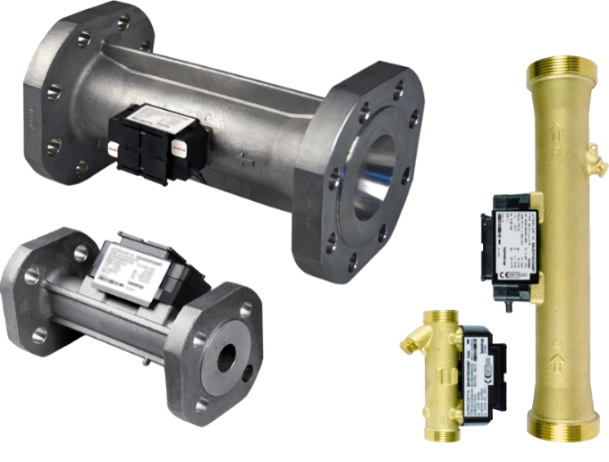
Durable, wear-free ultrasonic volume measuring device. Especially suitable for district heating applications (main meters, transfer stations, etc.) in billing transactions.
Ciepłomierze / Chłodomierze
Ultradźwiękowe
Smart City
Smart Building
Korzyści
- Durable, wear-free ultrasonic volume measuring device:
High measurement stability and operational reliability - Compact design:
Requires little installation space on site - High resolution of pulse values:
Precise instantaneous values - MID-approved, including initial calibration:
Approved for use in commercial transactions
Zastosowanie
- Particularly suitable for district heating applications (main meters, transfer stations, etc.) in billing transactions
- Replacement of mechanical impeller heat meters
- Heat consumption measurement in building services engineering
- Can only be used with MULTICAL® series calculators
Opcje
- Cable extension box (10–30 m) for signal cables between Ultraflow and Multical
- Pulse transmitter with its own power supply for cable lengths > 30m between Ultraflow and Multical
Pliki do pobrania
Cechy
- Nominal diameters:
Heating: DN 15 to DN 125 - Nominal flow rates:
Heat: qp 0,6 to qp 100 - Low pressure loss
- No moving parts
- Signal transmission to the computing unit and power supply to the volume measuring device via a 3-wire cable
- Medium temperature:
Heat: 15 to 130 °C
From 90 °C, a flange meter and the wall mounting of the calculator are recommended. - Type approval/certification:
- Heat: Conformity acc. European Measuring Instruments Directive (MID)
Product information
Technical Data
| ULTRAFLOW® 54 (DN 15 - 40) | |||||||||||||||
|---|---|---|---|---|---|---|---|---|---|---|---|---|---|---|---|
| Nominal flow rate | qp | m3/h | 0,6 | 0,6 | 1,5 | 1,5 | 2,5 | 2,5 | 3,5 | 3,5 | 6 | 6 | 6 | 10 | 10 |
| Nominal diameter | DN | mm | 15 | 20 | 20 | 20 | 20 | 20 | 25 | 25 | 25 | 25 | 32 | 40 | 40 |
| Connection thread on the meter | G...B | Inch | ¾ | 1 | 1 | flan-ge | 1 | flan-ge | 1¼ | flan-ge | 1¼ | flan-ge | flan-ge | 2 | flan-ge |
| Maximum flow rate | qs | m3/h | 1.2 | 1.2 | 3 | 3 | 5 | 5 | 7 | 7 | 12 | 12 | 12 | 20 | 20 |
| Minimum flow rate | qi | l/h | 6 | 6 | 15 | 15 | 25 | 25 | 35 | 35 | 60 | 60 | 60 | 100 | 100 |
| Starting value | l/h | 2 | 2 | 3 | 3 | 5 | 5 | 7 | 7 | 12 | 12 | 12 | 20 | 20 | |
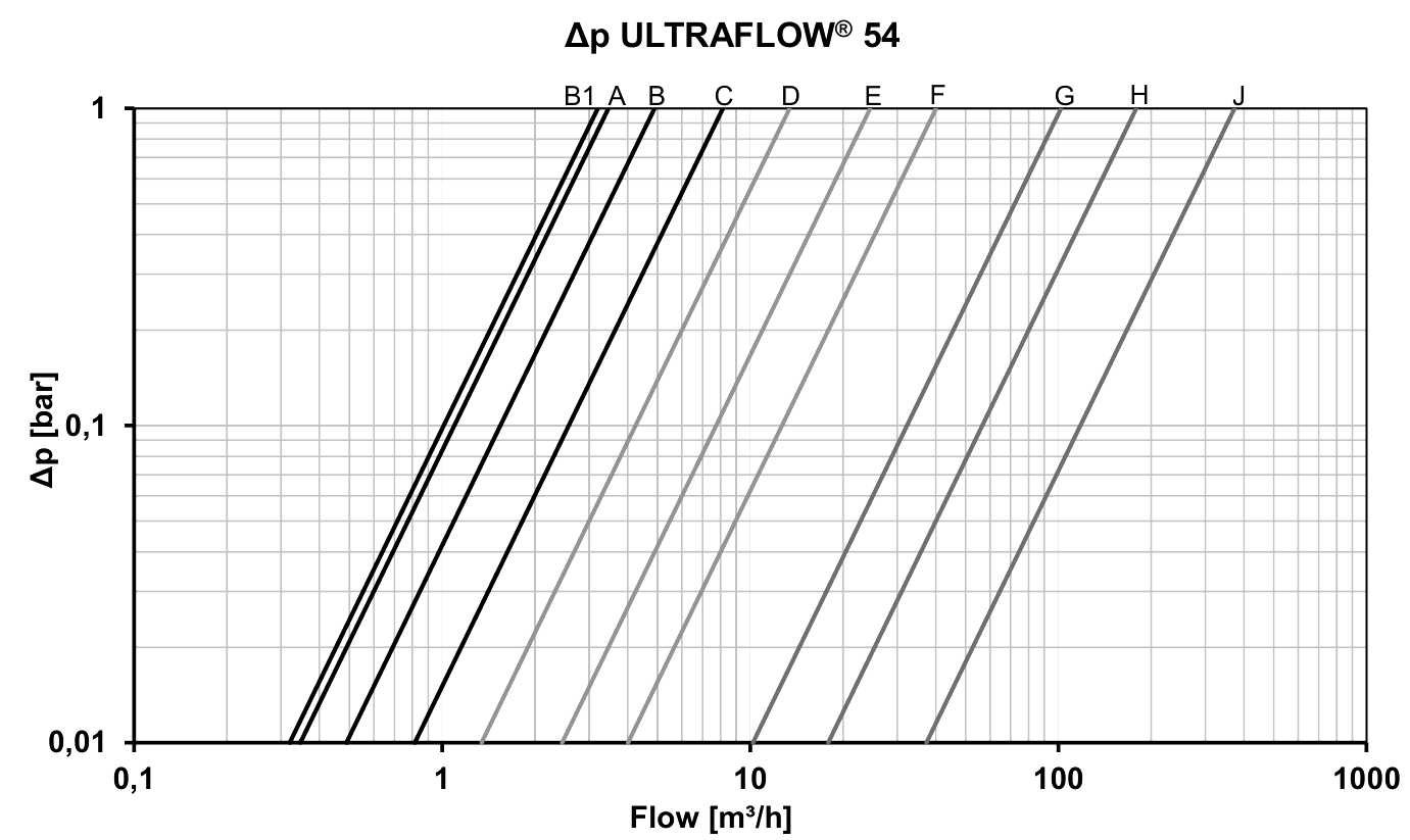
| Kvs value1) | m3/h | 3.5 | 3.5 | 4.9 | 3.2 | 8.2 | 13.4 | 13.4 | 13.4 | 24.5 | 13.4 | 13.4 | 40 | 40 | |
| Meter factor2) | p/l | 300 | 300 | 100 | 100 | 60 | 60 | 50 | 50 | 25 | 25 | 25 | 15 | 15 | |
| Graph | A | A | B | B1 | C | D | D | D | E | D | D | F | F | ||
| Maximum pressure | PN | bar | 25 | ||||||||||||
| Standard measuring range | qp / qi | 1:100 | |||||||||||||
| Protection class | IP65 | ||||||||||||||
1) q=kv x √∆p
2) The meter factor appears from the type label
| ULTRAFLOW® 54 (DN 50 - 125) | ||||||||
|---|---|---|---|---|---|---|---|---|
| Nominal flow rate | qp | m3/h | 15 | 25 | 40 | 60 | 100 | 100 |
| Nominal diameter | DN | mm | 50 | 65 | 80 | 100 | 100 | 125 |
| Connection | flange | flange | flange | flange | flange | flange | ||
| Maximum flow rate | qs | m3/h | 30 | 50 | 80 | 120 | 200 | 200 |
| Minimum flow rate | qi | m3/h | 0.15 | 0.25 | 0.4 | 0.6 | 1 | 1 |
| Starting value | l/h | 30 | 50 | 80 | 120 | 200 | 200 | |
| Kvs value3) | m3/h | 40 | 102 | 179 | 373 | 373 | 373 | |
| Meter factor4) | p/l | 10 | 6 | 5 | 2.5 | 1.5 | 1.5 | |
| Graph | F | G | H | J | J | J | ||
| Maximum pressure | PN | bar | 25 | |||||
| Standard measuring range | qp / qi | 1:100 | ||||||
| Protection class | IP65 | |||||||
3) q=kv x √∆p
4) The meter factor appears from the type label
Pressure loss
The pressure loss in a flow sensor is stated as the maximum pressure loss at qp.
According to EN 1434, the maximum pressure loss must not exceed 0,25 bar.
Mechanical data
| ULTRAFLOW® 54 | |
|---|---|
| Accuracy class | 2 |
| Electromagnetic environment | Fulfils EN 1434 class C, MID E1 and E2 |
| Mechanical environment | MID M1 and M2 |
| Ambient conditions | 5...55 °C, closed location (installation indoors) |
| Protection class | IP65 |
| Medium in flow sensor | Water – recommended water quality as in CEN TR 16911 and AGFW FW510 |
| Medium temperature5) | 15...130 °C or narrower range |
| Storage temperature (empty sensor) | -25...60 °C |
| Pressure stage | PN16/PN25, PS25 see marking |
| Straight inlet requirement | 0D (according to EN 1434) |
| Installation angle | Horizontally, vertically and at an angle |
5) At medium temperatures above 90 °C, the use of flange meters is recommended. At medium temperatures above 90 °C or below the ambient temperature, the calculator and Pulse Transmitter/Pulse Divider must not be mounted on the flow sensor. Instead wall mounting is recommended.
| Materials | |
|---|---|
| Wetted parts: | |
| Housing, thread | DZR brass (dezincification-resistant brass) CW511L with max 0,1 % Pb, implemented in 2024 |
| Blind plug | DZR brass (dezincification resistant brass) CW510L with max 0.1% Pb, implemented in 2024 |
| Housing, flange | Stainless steel, W.no. 1.4308 |
| Transducer (membrane) | Stainless steel, W.no. 1.4404 |
| O-ring | Ethylene propylene (EPDM) |
| Reflector base/reflector | Thermoplastic, PESU 30% GF and stainless steel, similar to AISI 304 or AISI 316/ Stainless steel, similar to AISI 304 or AISI 316 |
| Measuring tube | Thermoplastic, PESU – only qp 1,5 - 2,5 Thermoplastic, PESU 30% GF |
| Electronic housing: | |
| Base (flow sensor) | qp 1,5 - 2,5 Thermoplastic, PESU 30 % GF qp ≥ 3,5 Thermoplastic PC 10 % GF |
| Cover (flow sensor) | qp 1,5 - 2,5 Thermoplastic, PC 10% GF qp ≥ 3,5 Thermoplastic, PC 20% GF |
| Connection cable | Silicone cable (3 x 0.25 mm²) |
Approved meter data
| ULTRAFLOW® 54 | |
|---|---|
| Heat meter in accordance with MID-2014/32/EU | DK-0200-MI004-008, DK-0200-MI004-033 EU-Type Examination Certificate DK-0200-MID-D-001 MID-certified according to Module D |
| Standards and norms | EN 1434:2007/AC:2007 EN 1434:2015+A1:2018 EN 1434:2022 WELMEC 7.2:2022 |
| EU directives | Low Voltage Directive Electromagnetic Compatibility Directive Pressurised Equipment Directive (DN 50...DN 125 category I) |
| EN 1434 designation | Environmental class C Fast response meter |
| MID mechanical environment | Class M1 and M2 |
| MID electromagnetic environment | Class E1 and E2 |
| MID climatic environment | 5...55 °C, condensing, closed location (indoors) |
| MID accuracy class | 2 |
Accuracy
| ULTRAFLOW® 54 | |
|---|---|
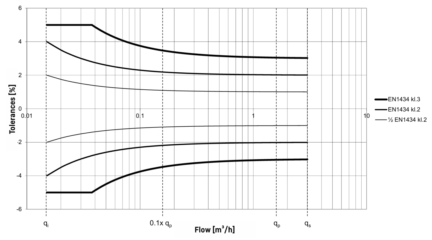
| Class 3 | Ef = ±(3 + 0,05 qp/q), but not above ±5 % |
| Class 2 | Ef = ±(2 + 0,02 qp/q), but not above ±5 % |
| Typical6) | Ef = ±(1 + 0,01 qp/q) |
6) Documented with DANAK-accredited certificate at flow qi, 0,1 qp and qp.
Flow sensor tolerances qp:qi 100:1 (qp 1,5 m³/h)
Dimensioned sketches
ULTRAFLOW® 54 flow sensors have a compact design and can be ordered with 2.5, 5 and 10 m signal cable to the calculator. Flow sensors of size qp 0.6...10 m³/h with threaded meter housings have the provision for built-in temperature sensors (M10x1 connection).
ULTRAFLOW® 54, G¾B and G1B
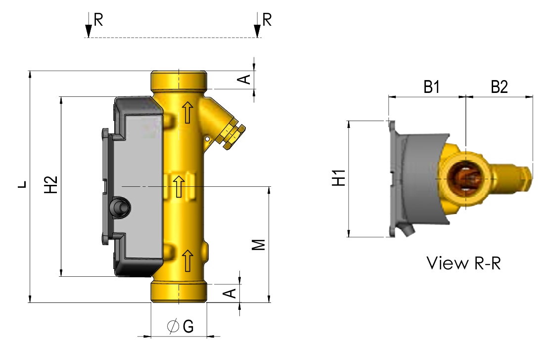
| ULTRAFLOW® 54, G¾B and G1B | |||||||||
|---|---|---|---|---|---|---|---|---|---|
| Nominal flow rate | qp | m3/h | 0,6 | 0,6 | 1,5 | 1,5 | 1,5 | 2,5 | 2,5 |
| Thread | G | Inch | G¾B | G1B | G¾B | G1B | G1B | G1B | G1B |
| Total length | L | mm | 110 | 130 | 110 | 130 | 190 | 130 | 190 |
| Dimension | M | mm | L/2 | L/2 | L/2 | L/2 | L/2 | L/2 | L/2 |
| Dimension | H2 | mm | 86 | 86 | 86 | 86 | 86 | 86 | 86 |
| Dimension | A | mm | 8 | 12 | 12 | 12 | 8 | 12 | 12 |
| Dimension | B1 | mm | 37 | 37 | 37 | 40 | 37 | 37 | 40 |
| Dimension | B2 | mm | 32 | 32 | 32 | 35 | 32 | 32 | 35 |
| Dimension | H1 | mm | 55 | 55 | 55 | 55 | 55 | 55 | 55 |
| Weight | app. kg | 0.41 | 0.46 | 0.51 | 0.53 | 0.51 | 0.61 | 0.67 | |
ULTRAFLOW® 54, G1¼B, G1½B and G2B
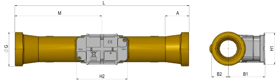
| ULTRAFLOW® 54, G1¼B, G1½B and G2B | ||||||
|---|---|---|---|---|---|---|
| Nominal flow rate | qp | m3/h | 3,5 | 6 | 6 | 10 |
| Thread | G | Inch | G1¼B | G1¼B | G1½B | G2B |
| Total length | L | mm | 260 | 260 | 260 | 300 |
| Dimension | M | mm | L/2 | L/2 | L/2 | L/2 |
| Dimension | H2 | mm | 89 | 89 | 89 | 89 |
| Dimension | A | mm | 16 | 16 | 31 | 40.2 |
| Dimension | B1 | mm | 58 | 60 | 60 | 63 |
| Dimension | B2 | mm | 20 | 20 | 24 | 29 |
| Dimension | H1 | mm | 55 | 55 | 55 | 55 |
| Weight | app. kg | 1.5 | 1.6 | 1.7 | 2.5 | |
ULTRAFLOW® 54, DN20 to DN50
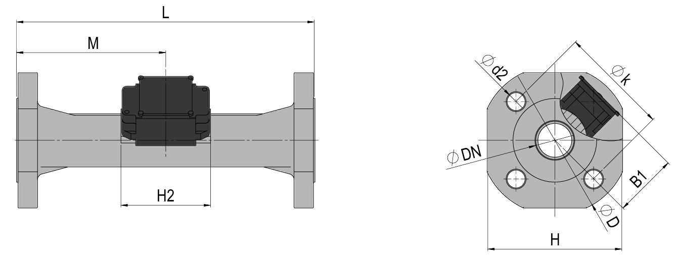
| Flange facing type B, raised face according to EN 1092-1 | ||||||||||
|---|---|---|---|---|---|---|---|---|---|---|
| Nominal flow rate | qp | m3/h | 1,5 | 2,5 | 3,5 | 6 | 6 | 10 | 15 | 15 |
| Diameter | DN | mm | 20 | 20 | 25 | 25 | 32 | 40 | 50 | 50 |
| Total length | L | mm | 190 | 190 | 260 | 260 | 260 | 300 | 250 | 270 |
| Total height | H | mm | 95 | 95 | 106 | 106 | 128 | 136 | 145 | 145 |
| Dimension | M | mm | L/2 | L/2 | L/2 | L/2 | L/2 | L/2 | 155 | 155 |
| Dimension | H2 | mm | 89 | 89 | 89 | 89 | 89 | 89 | 89 | 89 |
| Dimension | B1 | mm | 58 | 58 | 58 | 58 | D/2 | D/2 | D/2 | D/2 |
| Dimension | D | mm | 105 | 105 | 115 | 115 | 140 | 150 | 165 | 165 |
| Dimension | k | mm | 75 | 75 | 85 | 85 | 100 | 110 | 125 | 125 |
| Bolts | d2 | mm | 14 | 14 | 14 | 14 | 18 | 18 | 18 | 18 |
| Bolts Thread | M12 | M12 | M12 | M12 | M16 | M16 | M16 | M16 | ||
| Weight | app. kg | 3.2 | 2.9 | 5.0 | 5.0 | 5.2 | 8.3 | 9.8 | 10.1 | |
ULTRAFLOW® 54, DN65 to DN125
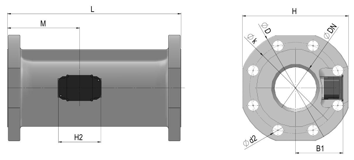
| Flange facing type B, raised face according to EN 1092-1 | |||||||
|---|---|---|---|---|---|---|---|
| Nominal flow rate | qp | m3/h | 25 | 40 | 60 | 100 | 100 |
| Diameter | DN | mm | 65 | 80 | 100 | 100 | 125 |
| Total length | L | mm | 300 | 300 | 360 | 360 | 350 |
| Total height | H | mm | 168 | 184 | 220 | 220 | 260 |
| Dimension | M | mm | 170 | 170 | 210 | 210 | 212 |
| Dimension | H2 | mm | 89 | 89 | 89 | 89 | 89 |
| Dimension | B1 | mm | H/2 | H/2 | H/2 | H/2 | H/2 |
| Dimension | D | mm | 185 | 200 | 220 | 220 | 270 |
| Dimension | k | mm | 145 | 160 | 190 | 190 | 220 |
| Bolts | d2 | mm | 18 | 18 | 22 | 22 | 26 |
| Bolts thread | M16 | M16 | M20 | M20 | M24 | ||
| Weight | app. kg | 13.2 | 16.8 | 21.7 | 21.7 | 28.2 | |
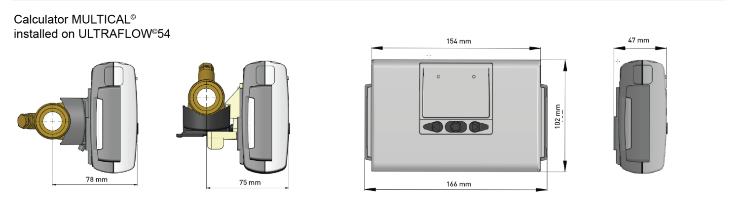
Installation note
Straight inlet
ULTRAFLOW® requires neither straight inlet nor outlet to meet the Measuring Instruments Directive MID 2014/32/EU, OIML R75:2002 and EN 1434. Only in case of heavy flow disturbances before the meter, a straight inlet section will be necessary. It is recommended to follow the guidelines in CEN CR 13582.
Operating pressure
To minimise the risk of measuring errors as a result of cavitation or air in the water, it is recommended to keep a sufficient static pressure at the flow sensor outlet of min. 1,5 bar (1,0 bar for qp 1,5 - 2,5) up to qp and min. 2,5 bar (2,0 bar for qp 1,5 - 2,5) at qs. This applies to temperatures up to app. 80 °C. It is particularly recommended to follow this advice during meter testing. In absence of cavitation, the flow sensor is typically functioning at lower operating pressure. Furthermore, ULTRAFLOW® must not be exposed to lower pressure than the ambient pressure (vacuum). This minimises the risk of transducer damage.
| Minimum recommended distances (best practice) | |
|---|---|
| Inlet section | 5 x DN |
| Outlet section | 3 x DN |
Installation positions
| Pipe: | horizontal |  |
| vertical |  | |
| inclined |  | |
| Head of the meter | to the side |  |
| ULTRAFLOW® 54 DN 15 – DN 125: | ± 45° |  |
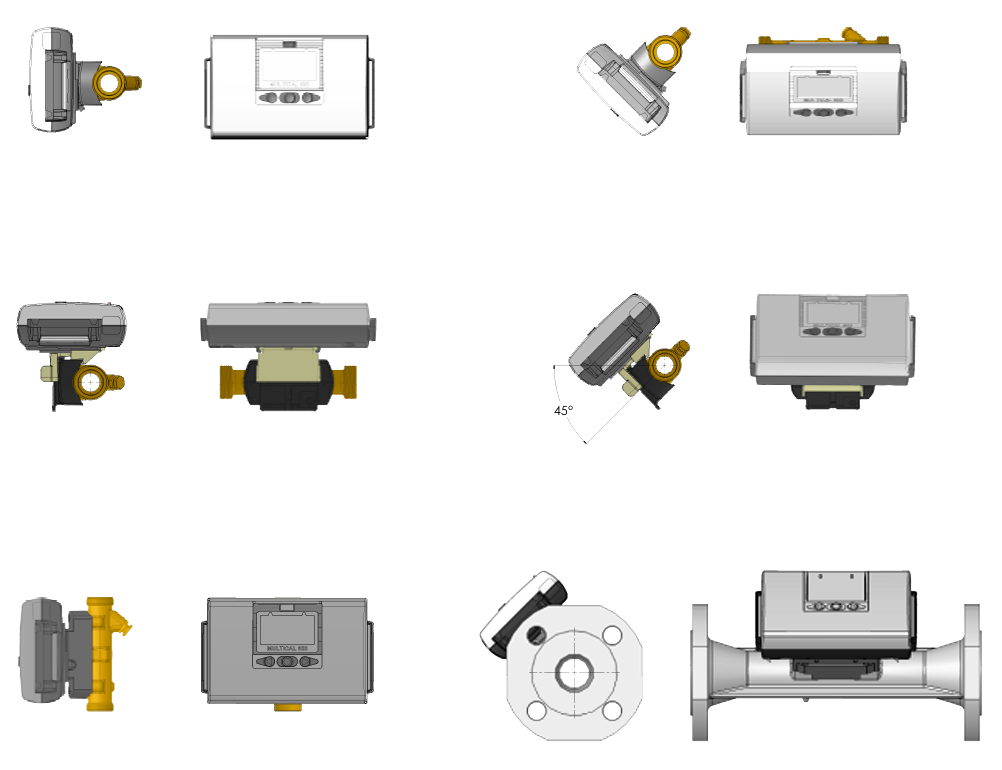

At a medium temperature above 90 °C, calculator and Pulse Transmitter must not be mounted on the flow sensor. Instead wall mounting is recommended.
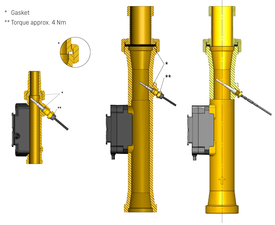
Coupling and direct short sensor mounted in ULTRAFLOW® 54
A temperature sensor can be directly mounted (M10x1 connection) in the outlet of all flow sensors with threaded meter housings (qp 0.6...10 m³/h).
Electrical connections
| ULTRAFLOW® 54 | → | MULTICAL® |
|---|---|---|
| Blue (Masse) / 11 A | → | 11 |
| Red (Supply) / 9 A | → | 9 |
| Yellow (Signal) / 10 A | → | 10 |